What Do We Want Our Aircraft to Do?

Greetings, friends!

So you remember that last post? That long, complex one from last time?

Yeah, I think I went a little overboard on that one. So today, instead of fancy graphs, we’ll be looking at what we want our aircraft to do, and how it will affect its design. Coming from an engineering perspective, graphs are a great way of converting raw data into a format our brains can interpret. However, there’s no substitute for pretty pictures, and  we’ll be studying plenty of those today. Think of this as a fun break. Or try. I’m doing my best here!

Lesson of the day: there’s no right or wrong to aircraft design. As long as you’re designing it to fly, you’re on the right track.

Blohm & Voss BV141. WWII German reconnassaince aircraft. Yes, it was a real thing. Luft46 (http://www.luft46.com/roart/ro141-2.jpg)

Don’t get me wrong – It’s quite possible design something that’s rubbish for your chosen role. And it’s perfectly possible to design an aircraft which isn’t really good at anything. Let’s say you want to fly 15 people about 120 miles over a mountain range, and you strap a pair of wings to a horse. Congratulations! Your aircraft can now mow the lawn for several years. Problem is, unless you’re somehow able to accelerate it to several dozen metres per second, it won’t fly. You would also have some pretty brutal stability problems, and a very unruly horse which would probably not survive the ordeal. You would also be a horrible person for trying. But if it could fly, then you would have designed an aircraft. Happy now?

Colomban Cri-Cri. Smaller than the engine you might find on a 787. Airliners.net (http://cdn-www.airliners.net/aviation-photos/photos/1/8/7/1720781.jpg)

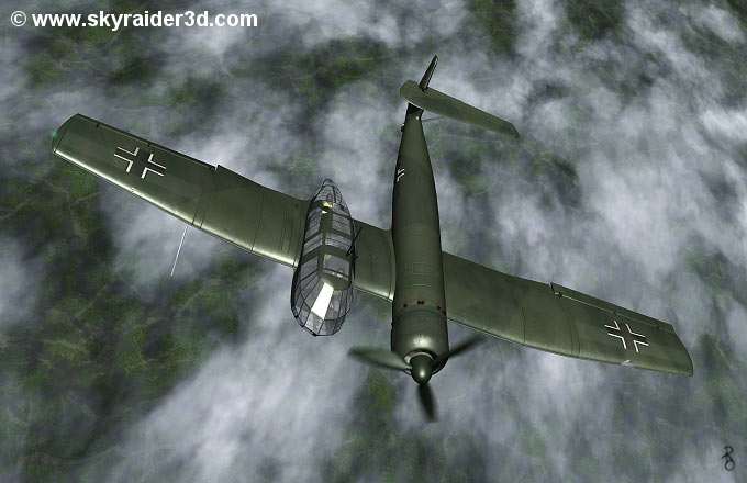
In all seriousness though, there are plenty of wierd and wonderful designs out there; from jet-powered biplanes to aircraft with no wings to “flying pancakes”. Many of these designs have useful attributes – the flying pancake’s structure could withstand apocolyptic events, and it had the potential for excellent manoeuvrability and slow-speed performance. The jet-powered biplane could (probably) achieve high altitude flight while maintaining a reasonably small wingspan, which could have been handy for storage and manoeuvrability.

Rutan Long-EZ. Very, VERY good at travelling long distances at speed, as long as you’re going in a reasonably straight line. Long EZ Air Shows (http://www.longezairshows.com/images/EZ_Info.jpg)

Understanding how to make an aircraft ‘good’ tends to require some level of knowledge on how flights work. Ideally, we’d like a manned aircraft to have:
– High maximum speed – allows us to go places fast
– Low stall speed – allows us to operate from smaller airports
– Low fuel consumption – fuel is heavy and ruinously expensive
– Low maintenance requirements – cheaply and rapidly fixed, tweaked and fuelled
– Low capital (buying) and running costs – no explanation needed
– Sound construction – nobody wants their aircraft to disintegrate on landing
– Positive stability and good handling qualities – aircraft won’t want to fly off on its own, fight the pilot, and spin out just above the ground
– The ability to carry a payload – people, cargo, etc.

These requirements are often contradictory. You want top speed? Add a bigger engine. You’ll also need to cough up more dosh. And more fuel, because that thing isn’t exactly going to be sipping it. Oh, and you’ll probably want to beef up your forward fuselage, because the extra torque from the prop is going to want to twist you as if wringing out a cloth. While trying to pull your nose off. And vibrating like a million ringing mobile phones. And because all this weight must be counteracted by lift, you can’t fly particularly slowly anymore, so suddenly you can’t fly to that one airport which would have been perfect.

Gee Bee Model R. A very big engine with an aircraft bolted on. Was known for being very fast and getting its pilots killed. gkbgraphics (http://www.gkbgraphics.com/wp-content/uploads/2013/04/Gee-Bee-Racer.jpg)

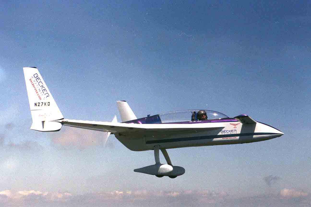
I have been told that an aircraft is a thousand flying compromises. The Europa is a good example of a thousand compromises done properly. It’s designed to have a very small cross-section, which reduces fuel burn and increases top speed, and uses a specialised wing section which produces very low drag in the cruise. It’s also a homebuild, so is WAY cheaper than a production aircraft would be. Downsides include a sharp stall, the requirement to build it yourself, and various legal restrictions (no low-light flying, no flying through or over clouds, etc). Arguably the two-crew limit is also a compromise, as it can’t carry as much as a good four-seater.

SpaceShipTwo. Technically an aircraft (and legally defined as a glider), as it must guide itself to ground unpowered. Genius design. Virgin Galactic (http://www.virgingalactic.com/uploads/134089827595572/original.jpg)
Airbus E-Fan. Designed very specifically to be powered by the magic of electrickery. Production variants will save a LOT on fuel. Global Aviation Report (http://globalaviationreport.files.wordpress.com/2014/04/efan-ciel5-20130522.jpg)

Now, we’re only going to design a simple model aircraft, so factors such as maximum speed and fuel consumption are not necessarily priorities. We want a simple, fun aircraft that flies well. We don’t need to go anywhere fast, and if our aircraft runs out of juice, we can just recharge. However, landing at slower speeds is much easier, and also mitigates landing damages, such as scratches or dents from rough grass or gravel. Something is bound to break eventually, so we’ll need to be able to access parts to replace them. We don’t want to spend too much money on this – ideally, we don’t want to spend anything. And we certainly don’t want to take our aircraft home in a binbag.

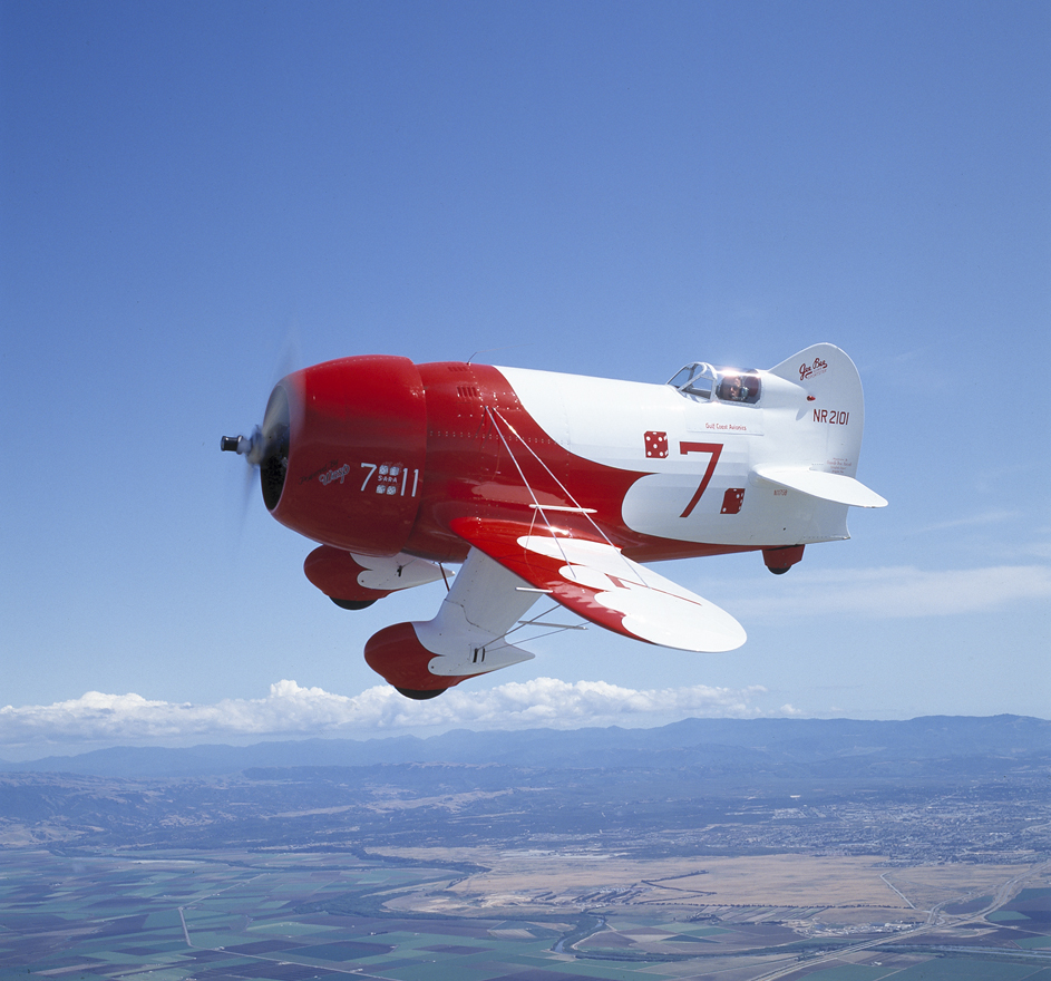
So, we start to get the picture that an aircraft must balance its compromises on a delicate set of scales, depending on its intended function. An airliner uses (proportionately) small wings to achieve high cruise speeds and fuel efficiency at the cost of short field performance. A bush plane sacrifices fuel efficiency, high cruise speeds and payload capacity for a rugged structure, simplicity and the ability to take off and land on a dime. If aircraft are designed for very specific purposes or functions, they tend have more biting compromises. The Harrier, while a brilliant feat of engineering, compromises fuel efficiency, range, payload capacity and top speed to gain its vertical capabilities. An aerobatic aircraft such as the Extra 300 is obscenely manoeuvrable and can accelerate like the cat you just trod on, but won’t have anything resembling fuel efficiency, range or cargo capacity.

PZL M-15 Belphegor. The ultimate in “What in God’s good name were they thinking?” design. Samoloty w Lotnictwie Polskim (http://www.samolotypolskie.pl/uploads/Products/product_2373/pzl-m-15-belfegor_src_2.jpg)

So: what do we want our model to do?

Well, ideally it would have a low stall speed for easy, calm flying. This will require large wings to provide the extra lift, thereby compromising our top speed – but that’s not really a concern for this type of model. Of greater concern would be that the model would suffer gusts and turbulence with much less… elegance. Annoyingly, this could make landings trickier in windy situations, but it’s a necessary sacrifice. We’ll just have to be careful on windy days. Since this is going to be a model that (ideally) anyone can fly, we’ll need a good deal of positive stability and benign handling characteristics. Now, for reasons I should get round to explaining later, this will sacrifice some manoeuvrability and lift. The latter point will sacrifice some low-speed performance, or we could increase the wing size a tad to compensate. Structurally speaking, we’ll want a rugged airframe to compensate for rookie antics and Sod’s law. It will be simple, which will have the double impact of reducing complexity (so less stuff can break) and generally making maintenance easier. Bear in mind  that we’ll need to access the electronics regularly for charging. Let’s see… we won’t need it to take a payload, and fuel won’t be a problem. Our aircraft will be powered with electrickery, as some aeromodellers like to refer to it. This is partially because I’ve never dealt with glow engines before, but largely because electric power trains are comparatively safer (improper care still results in fire and explosions), easier to manage, and often much cheaper.

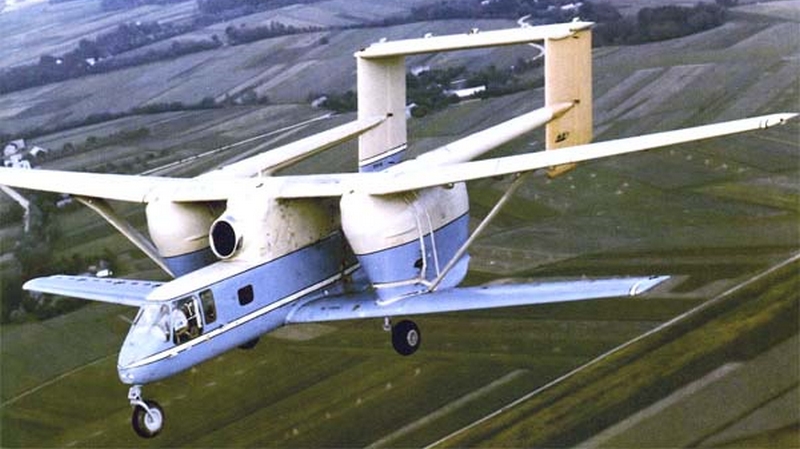
Grand! We’ve established that we want fairly big wings to provide our lift, a simple and easily-accessed structure, and a good lick of stability with quality handling. We have established what we want. Further down the line, we’ll establish how to achieve it. In the meantime, have a picture of a flying lawnmower.

Behold. It is also a thing. Science Metropolis (http://www.sciencemetropolis.com/wp-content/uploads/2008/07/dsc_6817.jpg)

And remember: don’t be a bad person to horses.

Basics of Wings: Part 3

Hello again! First of the new fresh posts to this blog. Hopefully these past few days have been sufficient recovery time from that last monster of a post. Wings are funny like that, and we’re only covering the barest minimum of functional basics… pretend I didn’t just say that.

So last time, we discovered that the total lift generated by wings is focussed around a point. Well guess what? This point moves backwards and forwards!

I’m sorry, but it’s true. In fact, in certain situations, this point wander off to an infinite distance in front of the wing. Tilt the wing a bit, and it shoots off to infinity in the other direction.

Put your worries to rest, though, because it’s controlled by a very simple (but brilliant) concept called moments. No, not moments in time (it had me confused for a while at first). We’re talking levers here. You know how taking a wooden crate apart is way easier with a crowbar than with your hands? That works because moments make it so. And now, let’s go back to that blessed see-saw analogy. I know, it gets old, but see-saws are bloody brilliant at demonstrating this stuff.

Put simply: Moment = Force x Distance

Moments in action. BBC (http://www.bbc.co.uk/bitesize/ks3/science/images/weights_on_a_seesaw.gif)

Let’s set some rules to fix how they work.

  • If we increase the weight on one side, we’ve got to move it closer to the reference point (in this case, the pivot) to keep the moment constant (make sure the value doesn’t change)
  • If we reduce the weight on one side, we’ve got to move it further away from the pivot to keep the moment constant
  • If the moment on one side = the moment on the other, then the see-saw will remain still.
  • If the moment on the left = bigger than the moment on the right, then the see-saw will rotate to the left (in the direction of the greater moment – anti-clockwise, in this case)
  • If the moment on the right = bigger than the moment on the left, then the see-saw will rotate to the right (clockwise, in this case)

One easy way of remembering the first three points is this:  for a constant moment, an increase in force means a decrease in distance from the reference point, and a decrease in force means an increase in distance from the reference point.


Got it? I hope so. If not, that BBC article I grabbed the illustration off seems a reasonable place to start. I’m afraid that to understand wings, one must first understand moments. To reiterate: THIS IS SOMETHING YOU CANNOT SKIP.


Okay, if you’re reading this, then you either understand moments, or you’ve given up and are cheating. Or you’re skim-reading, and… you know, my parents always told me not to judge.

So, dear reader (can I call you dear reader? I’m going to go with yes), we established that the centre of pressure (the point along the wing at which lift does its lifting thing) moves. But how do we tell where that little rascal has gotten off to? And how do we predict where it’s going to go? Well, for present purposes, it depends on the angle at which the wing meets the airflow. We call this the angle of attack.

Angle of attack, Greek symbol alpha. Wikipedia (http://upload.wikimedia.org/wikipedia/commons/thumb/6/6d/Angle_of_attack.svg/305px-Angle_of_attack.svg.png)

Those lines represent the paths of the incoming air, and the Greek symbol alpha represents the angle between it and the wing. If the wing tilts upwards, it is said to have a positive angle of attack, and will be generating lift. If it’s tilting down, the angle of attack becomes negative, and the wing will start producing negative lift (pushing the aircraft down). If it’s pointing straight into the airflow, the angle of attack is 0.

And now that’s sorted, we’ll introduce the Aerodynamic Centre. This sweet spot is the point around which the centre of pressure moves. For most aerofoils (the 2D shape you see below), it resides more or less 25% of the chord length back from the leading edge.

Aerodynamic Centre. Modified from original source. adamone.rchomepage.com (http://adamone.rchomepage.com/index5.htm)

Are you ready for some brain hurting? I’ll assume that’s a yes.

The Aerodynamic Centre is the point at which the lifting moment remains constant.

Don’t panic! Let’s go back to the moment ground rules we set out earlier. We know that a constant moment requires an increase in force to be matched with a decrease in distance from the reference point, and vice versa.

The wing’s aerodynamic centre is treated in the same way as the pivot – it is our reference point. If the moment around the aeodynamic centre must remain constant:

  • If lift increases, then the centre of pressure must move closer to the aerodynamic centre.
  • If lift decreases, then the centre of pressure must move further away from the aerodynamic centre.

So, taking this to two logical conclusions:

  • The centre of pressure is closest to the aerodynamic centre when the wing is generating its maximum lift (positive or negative)
  • The centre of pressure is furthest from the aerodynamic centre when the wing is generating zero lift. In fact, it’s infinitely far away. Crazy, right?

Now, we know that lift is connected to the wing’s angle of attack. Making some reasonable assumptions, and as long as the wing is flying normally:

  • The further the angle of attack is from 0, the more lift is generated, and the closer the centre of pressure is to the aerodynamic centre. Remember, this applies whether the wing is pointing up or down!
  • The closer the angle of attack is to 0, the less lift is generated, and the further the centre of pressure is from the aerodynamic centre*.

*Just a note  – many wings actually generate 0 lift at negative angles of attack, depending on their designs. We’ll go over this later.


Resorting temporarily to second person, you’re just going to have to bear with me on this one. This might seem like a pointlessly complex and unnecessary topic, but it’s absolutely crucial for keeping aircraft flying controllably. And anyway, that’s the worst of wings covered. Next time, we’ll get to look at some pretty graphs which will tell us all we need to know about how a wing behaves.

Basics of Wings: Part 2

And the last of the Sett-imported posts rolls in. New content soon!

Subject! Wings! Yes! You’ve got to love wings. They allow us to fly and look pretty cool (in my opinion). You can even hang things like engines on them. Marvellous! We know they generate lift, and that’s great. But alas, it’s not that simple. We need to go deeper. I’m about to introduce you to the centre of pressure. Remember, this hurts me more than it hurts you.

Let’s imagine a wing flying through the air. We know it generates an area of lower pressure on its upper surface. We know this pushes the wing up. But it’s not like someone plonks their hand on the lower surface and just hauls the thing up. The pressure isn’t evenly distributed; it varies in magnitude along the chord (front-to-back length, as opposed to span, which is root to tip) of the wing. Let’s see how:

(Wikipedia: http://en.wikipedia.org/wiki/Lift_%28force%29)

Look to the wing’s upper surface, towards the leading edge (the front). See how the air particles are moving fastest here? As we learned from the last post, that faster speed means there must be a corresponding pressure drop, which means: lots of lift! But look! It starts to slow down again past a certain point. As the air slows down, pressure increases – you get less lift as you move further back. The further back you go, the higher the pressure gets, until it matches the pressure on the lower surface – this section of the wing isn’t producing any lift.

This is where the important steps happen. Pay attention. You… nouns.

  • We know some sections of the wing will experience a stronger lifting force than others.

LiftComponentsdef3153caad3b3d5261cc0f244

(VERY rough representation of lift components. Symmetrical sections wouldn’t behave like this!)

  • Combine these force components together, and you have a resultant (overall) lifting force. This is the wing’s lift.

LiftComponentsa266f9ce6f6f285e1db94c664f

(VERY rough representation of total lift magnitude and point of action)

  • This lift force is focussed at a certain point along the wing chord.
  • This point is known as the centre of pressure.

Whew! That took a hell of a long time to figure out how to explain.

Right. So we know the wing is basically being pushed up through a specific point. It is REALLY REALLY IMPORTANT to know where this point is. Here’s why: you have to balance your aircraft. All solid objects balance around a certain point – this is known to engineers as the centre of gravity. This is where an object’s weight is focussed, in the same way as the mid-point of a see-saw. To keep the see-saw level, you’ve got to have the force pushing it up directly on top of that mid-point. Move in either direction, and the see-saw will start to rotate. In the same way, if an aircraft’s overall lifting force isn’t sitting on the centre of gravity, it will stop flying straight and level and start revolving around it, which can have perilous implications.

In the next post, we’ll learn how to calculate where the centre of pressure lies.

Basics of Wings: Part 1

So, by this stage we know what the wings are for – generating the lift that keeps us airborne. Fantastic!

There are, however, a few caveats. Wings behave in a very specific way which, if you don’t want to look like a dolt, must be accounted for in the design process. To start off with, let’s look at how that lift is made.

General consensus holds that wings generate lift in two distinct ways.

  • Newtonian lift. Have you ever stuck your hand out of a car window, and angled it upwards? If the car was moving fast enough, you’ll probably have noticed that your hand was pushed backwards and up. This occurs because the incoming airflow was being deflected downwards slightly by your angled hand. Since all forces have an opposite and equal reaction, your hand would have subsequently been pushed in the opposite direction. Congratulations – for a brief window in time, your hand was generating Newtonian lift. You made a wing. That wasn’t so hard, was it?
  • Bernoulli lift… this one can be tricky to get your head around, so don’t worry if you don’t get it. Basically, as the airflow hits the wing, it is split into two streams: one going over the wing’s upper surface, and one going over the lower one. The shape of the wing causes air to flow faster over the top surface than the lower one (you’ll just have to go along with this – the explanation is way beyond the scope of this blog). This causes a pressure drop above the wing, which results in a pressure differential.ExplainLiftUSA35BAerofoil3509c0709ed0f74And the result? Imagine you’ve got one hand on each surface, both pushing the on wing with equal force. That wing isn’t going anywhere. Now reduce the force being exerted by the upper hand (the one pushing the wing down). Since the hand pushing the wing up is now exerting more force than the one pushing the wing down, the wing rises.

We now have a basic picture of how lift is generated. Next time, we’ll go over what we can do to deal with some of the craftier characteristics of this wonderful force.

On a Wing and a Tail…plane… and fin. That title didn’t work out so well.

The wings, fin and tailplane are the vital surfaces which keep the aircraft:

  • Flying
  • Flying straight

Lose anything mid-flight, and things become very bad very quickly. Let’s see why.

Flying Surfaces

Wings: we’ll go into the physics later, but for now, all you need to know is that they provide all the delicious lift needed to make us fly. Lose your wings, lose your lift. And fall.

As for the tail – it’s all about stability. The whole tail section of the aircraft is collectively known as the ’empennage’, which includes the fin (the vertical one) and the tailplane (the horizontal one). In essence, the empennage keeps the aircraft controllable.

The fin and attached rudder serve two different purposes: the fin acts like a weathercock to push the aircraft heading into the local wind direction, and the rudder provides control to make sure the pilot can still control where he or she is going. The rudders on a boat and aircraft have the exact same purpose. The really nifty bit is that as the wind gusts or increases in strength, the weathercocking effect of the fin pushes the aircraft’s nose (the front bit) into the incoming airflow to compensate. Imagine landing with the wind blowing across the runway. The wind is trying to drag you with it, out of line with the runway and into a field of helpless kittens. But wait! Your fin causes you to weathercock into the airflow, allowing you to defy the wind and keeping you moving towards that glorious asphalt. Now you and the kittens are safe. Without a fin, the aircraft would wander about all over the place, and probably crash somewhere, which would make for a rubbish day.

The tailplane, while more complex in its workings, performs a similar function. For reasons I’ll explain later, most aircraft actually need their tails to produce negative lift (i.e. pushing downwards) to keep flying straight. The tailplane provides pitch (facing up or down) stability, and the attached elevators provide control to the pilot. Without a tailplane, most aircraft would plough straight into the ground. Without elevators, the only way to get an aircraft flying straight and level would be to fly at a certain (very fast) speed. Landing at these speeds would be disastrous.

So there you have it. Don’t lose your wings, fin or tailplane, or bad things will happen.

Just a note: we won’t be covering tandem wing or similar configurations. If you don’t know what this means, just ignore this block.

Aircraft… Wait, What?

Right, let’s get these posts across to their new home!

I won’t sugarcoat it – aircraft design can be hard. Getting to grips with the theory from scratch can be profoundly frustrating and irksome at times. On the flipside, you can sound pretty clever. On the flipside flipside, people do start to glaze over when you talk about it – believe me, I know.

So, to simplify things, we’ll look at what’s been done before, and why. Instead of theory, we’ll study a design that we know works splendidly: the Cessna 172.

Cessna 172: Wikipedia (http://upload.wikimedia.org/wikipedia/commons/thumb/2/29/Cessna_172_Skyhawk_%28D-EDDX%29_02.jpg/800px-Cessna_172_Skyhawk_%28D-EDDX%29_02.jpg)

The 172 is the most popular aircraft on the planet. It’s designed to be easy and safe to fly, and is widely credited as being something of a jack of all trades. Let’s go over some of the more obvious details from this photo:

  • Notice how curvy the 172 is. Moving air doesn’t tend to like encountering sharply-changing surfaces, and typically causes extra drag when it does. By keeping the aircraft as smooth to the air as possible (AKA ‘streamlined’ or ‘clean’), the design can slip through the air while keeping drag losses to a minimum. This increases fuel efficiency and top speed.
  • See the way the wheels are covered over? They’re called spats. They reduce drag (thus keeping fuel efficiency up), and look pretty. That’s… pretty much it.
  • The reason the wing is above the cabin, rather than below? It improves stability (I’ll explain later), and allows the pilot to see the ground, which is very handy for takeoffs and landings. It does come at the cost of not being able to see anything directly above the wings though, which can be a bummer if you end up ascending into another aircraft.
  • Those struts joining the wings to the fuselage – funnily enough, they’re called wing struts. During ground operations, they support the wing in exactly the same way as how a shelf bracket supports a shelf – they operate in compression, keeping the wings from falling to the ground. However, this situation is reversed in flight. The wings are trying to pull the aircraft up, so the struts must keep them attached to the fuselage – they are now operating in tension, keeping the wings from flying off into the blue yonder, which would be very bad.
  • Starting at the rear window, you’ll see a ridge that slowly gets bigger as you move further back along the aircraft, merging into the fin (the bit that sticks up from the tail). This is called a strake, and is used to help the fin prevent spins. If uncorrected, spins can be fatal manoeuvres in which the aircraft basically gets stuck rotating around its mid-point and starts falling out of the sky.
  • As far as I’m aware, sweeping the fin back on an aircraft of this speed is typically done for aesthetics and doesn’t really provide any serious performance benefits, i.e. it looks pretty and that’s it.
  • There are three wheels, with one sitting in front. This is called a tricycle undercarriage (who’d have thought, right?), and allows for the aircraft to operate on the ground with the noise pointing straight ahead – thus letting the pilot see where he or she is going while on the ground. It also allows for brakes to be used without flipping the aircraft over on landing.
  • Notice how there’s not much aircraft ahead of the wing, but plenty behind it? This is done to help the aircraft balance properly, like a see-saw. That engine is flipping heavy. Having the tail surfaces further behind the wings also increases their stabilising effects (again, I’ll explain later).

Well, hopefully that wasn’t so bad. With a few basic design points, the theory which we’ll address later should be a little less bitey. Next time, we’ll look at why we have wing and tail surfaces, and what it is exactly that they do.


Hello, Internet. Again. Sort of…

After Sett flipped out on me and refused to delete bad posts, I decided to switch to WordPress instead. I’ll be copying stuff across over the next few days.

Anyway…

Greetings! Salutations! Opening remarks! This blog is written with the intent of teaching the basics of aircraft design to non-engineers. To simplify the topic, we’ll be looking at model aircraft, specifically. Sticking a human in the cockpit entails all sorts of complexities.

Theory can be rather dull, so we’ll be applying what we’ve learned to design a flying model aircraft. Awesome stuff.