I’ve been waiting to use that title for some time now. Packing references into these blog posts makes them so much less dull to write, you know. Anyway…
Penultimate post on wing design! Turns out the wing couldn’t lift quite as much as I had hoped for, and it needs a redesign. Let’s find out why. Onwards!
Why Lift at All?
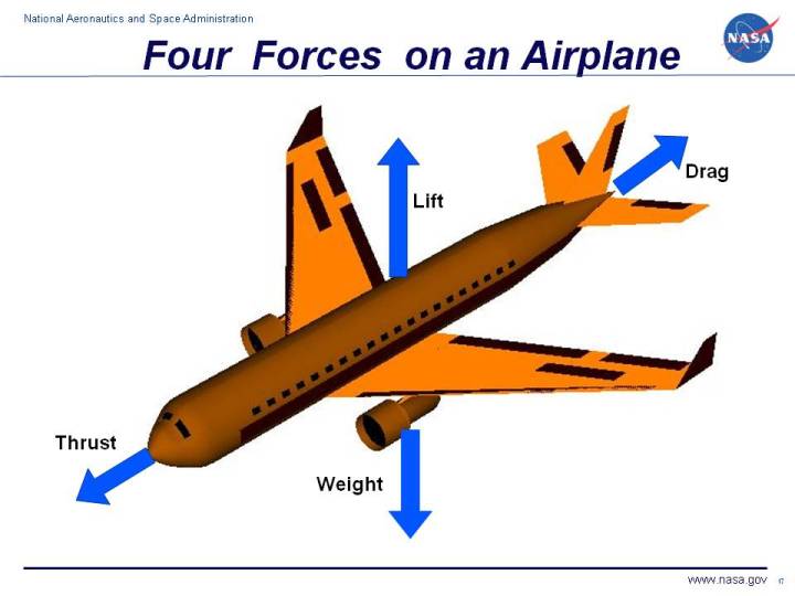
Oh yeah, I forgot to explain why lift was really important in the first place. It’s the force that keeps aircraft from falling down. There are four forces acting on an aircraft:

- Thrust is the force pushing the aircraft forwards, and is produced by the engines. Usually, thrust is generated by spinning things at hair-raising speeds.
- If thrust is Holmes, then drag is Moriarty. As the aircraft moves forwards, it collides with air molecules, which exert frictional forces which try to pull it to a stop. Go away. Moriarty. You’re ruining everyone’s fun again.
- Weight doesn’t really need an explanation. It is the anchor that tethers us to this rock; our Magikarp, if you will.
- Lift fights against weight to keep us up. The Garydos to our Magikarp.
In short, to keep flying, our plucky aircraft will have to produce enough lift to counter or exceed its weight. If its weight is even slightly greater than its lift, the aircraft will accelerate downwards, which (unless you intend to land) is generally considered a bad thing.
Given its size, our aircraft will probably have a mass of around 0.8kg, give or take a few hundred grams. Weight is a force, so Force = Mass x Acceleration becomes Weight = Mass x Gravitational Acceleration. Gravitational Acceleration at sea level is 9.807m/s^2, so:
Weight = 9.807 x Mass = 7.846 Newtons
Therefore our aircraft should be producing around 7.8 Newtons of lift.
Bear in mind, the figure is just an estimate, based on previous experience and guesswork. We’ll only start to get an accurate idea of the aircraft’s weight once we start working on its structure. But hey, it’s a start.
Wing Lift Curve
We left off with the necessary formula for calculating our wing lift curve. This is very important, as it will allow us to track just how much lift our wing is producing, which is itself very important for balancing our aircraft, designing the tail, and predicting how fast our stall speed (i.e. minimum flying speed) is going to be.
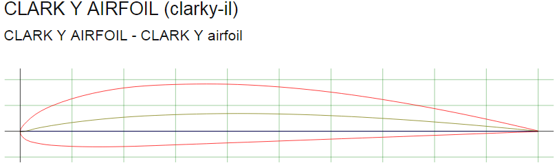
Wing Lift Curve = 0.7485 x Foil Lift Curve

Where that red line is the foil lift curve. The foil lift curve can be represented mathematically as:
Foil Lift Curve = Change in Aerofoil’s Lift Coefficient ÷ Change in Angle of Attack.
By comparison, the wing lift curve will look something like this when plotted on the same graph:

I’m going to do the heavy lifting here and determine just what the foil lift curve is for you. To be more precise, I’ll be using aerodynamic data generated by the previously-introduced XFLR5, and running some of it through Excel. Here’s why:

It’s going to involve some fiddling in the previously-introduced XFLR5, some data transfer to Excel, and simple maths – I can’t really explain without a video or a long, boring wall of text. Wish me luck.
Ok, it looks like the lift curve is pretty much straight from 0 to 7 degrees angle of attack. The coefficient of lift at Alpha=0 is 0.3605, and at Alpha=7 is 1.109.
Applying maths to the problem, we have:
Foil Lift Curve = Change in Aerofoil’s Lift Coefficient ÷ Change in Angle of Attack.
So:
Foil Lift Curve = (Final Lift Coefficient – Initial Lift Coefficient) ÷ (Final Angle of Attack – Initial Angle of Attack)
Foil Lift Curve = (1.109 – 0.3605) ÷ (7-0)
Foil Lift Curve = 0.7485 ÷ 7
Foil Lift Curve = 0.1069
And judging from the graph I can’t be bothered to include, it looks like the Zero-Lift Angle of Attack is -2.257.
We’re on! So the Wing Lift Curve must be:
Wing Lift Curve = 0.75 x Foil Lift Curve
Wing Lift Curve = 0.75 x 0.1069
Wing Lift Curve = 0.08018
Woo! This means we can finally calculate the amount of lift our wing is producing!
Wing Lift Coefficient = (Wing Lift Curve x Angle of Attack) + Y Intersect
Wing Lift Coefficient = (0.08018 x Angle of Attack) + Y Intersect
Ah… forgot that step. We need to find the lift coefficient when the angle of attack is 0 (the so-called Y Intersect). Fortunately, we already know the zero-lift angle of attack, so if we use this as a baseline, we can solve the formula. We set the parameters:
- Angle of Attack = -2.257
- Coefficient of Lift = 0
And we plug these numbers back into the formula:
Wing Lift Coefficient = (0.08018 x Angle of Attack) + Y Intersect
0 = (0.08018 x -2.257) + Y Intersect
0 = -0.1810 + Y Intersect
Y Intersect = 0.1810
Which finally combines to make:
Wing Lift Coefficient = (0.08018 x Angle of Attack) + 0.1810
Dihedral
Since dihedral only has positive effects for stability, there’s no way of knowing how much we’ll need to use before moving into the later stages of design. Based on previous experience, I reckon we would be prudent to design the wing with 3 degrees of dihedral already built in. If we don’t need it, we can remove the dihedral and gain a little extra lift. If we need more, then we won’t lose a lot of lift in the process.
If 0 degrees of dihedral leaves us with 100% lift, and 90 degrees dihedral leaves us with 0 lift, then a single degree of dihedral reduces lift by 1.111%.
Therefore, the 3 degrees of dihedral we want for stability reduces total lift available by 3.333%.
Wing Tips
We’ll be working some rounded tips into our wing. They shouldn’t add more than 5% to the span, and will give us a small increase in lift – both from the increased wing area and the reduction in wasted lift. They might be a little challenging to design in XFLR5, but they’re not too hard to build in practice. Also, it looks better – models like ours tend to benefit from looking old-school.
Heavy Lifting
We can now calculate our wing lift coefficient for a given angle of attack. Note: this formula only applies if the wing is behaving normally – a wing approaching the stall will perform very differently! Fortunately, we only really need the formula to calculate what’s going on in cruise conditions.
So how much lift is our wing actually producing in the cruise? We’ve already worked out the lift formula, so let’s dredge it back up:
Lift = 0.6125 x Coefficient of Lift x Wing Area x (Airspeed^2)
Since we’ve already set the dimensions of our wing, we can calculate the wing area.
Wing Area = Wing Span x Wing Chord
Wing Area = 1.25m x 0.21m = 0.2625 metres squared
Plugging this back into the lift formula:
Lift = 0.6125 x Coefficient of Lift x 0.2625 x (Airspeed^2)
Lift = 0.1608 x Coefficient of Lift x (Airspeed^2)
This is the simplest form of the formula, but it’s not all that useful unless we can relate the lift to the angle of attack our aircraft will be flying at. Plugging in the formula for coefficient of lift vs angle of attack:
Wing Lift Coefficient = (0.08018 x Angle of Attack) + 0.1810
Lift = 0.1608 x [(0.08018 x Angle of Attack) + 0.1810] x (Airspeed^2)
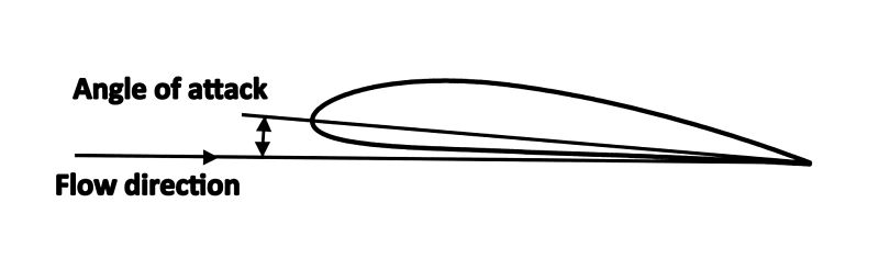
A few lines of maths, and now the formula is looking much less wordy and more numbery. Let’s plug in the cruise condition figures and see what comes out. Since we’re only figuring this out for the wing, we don’t have to take an angle of incidence into account (if you have no idea what’s going on: see the last post or alternatively think about your place in the universe).
- Angle of Attack = 0 degrees
- Airspeed = 6m/s
Lift = 0.1608 x [(0.08018 x 0)+0.1846] x (6^2)
Lift = 0.1608 x 0.1846 x 36
And taking the 3.333% loss in in lift:
Lift = 0.1608 x 0.1846 x 36 x 0.9666
Lift = 1.033 Newtons
Divide by gravitational acceleration at Earth’s surface (9.81 metres per second squared) and we have a wing that can lift 108.9 grams. This wing could potentially lift a pear.

Physics, if you were a person, I would rub tabasco into your eyeballs and call you a horrible creature who should be ashamed for even being alive. But I think that act would make me a horrible creature, and hypocrisy is something that really rustles my jimmies. Besides, we love physics really. It’s just so very clever.
At first I thought I got the maths wrong, but no. It’s just the way the formulae worked out, and numbers don’t lie (I have been informed that hips also do not lie, but have yet to confirm this). But this is a key step in the learning process – making the really, really annoying mistakes that make you really stroppy, then kind of bummed out, before realising it’s not so bad and fixing it with a few adjustments. As William Blake once said: “there is no mistake so great as the mistake of not going on.” And go on we must. I have too much invested in this alcove of the internet; turning back now would be an outrageous act of moral turpitude. And you, dear reader; you, who have invested your precious time in this dusty abode in pursuit of the understanding of aerial vehicles – your attention must not be allowed to go to waste. We shall walk this perilous road of learning, through the treacherous wastelands of ignorance, to stand together in the glorious light of knowledge. We shall!
But not quite yet, because this one has already gone on for far too long. And spoiler alert: I’ve already figured out how to squeeze out that extra lift. Also, the wing kills Dumbledore on page 314.
Well this has been amusing. I suppose I will get on with the next post; hopefully we’ll have this wing thing sorted before the end of the week. In the meantime, consider this: what exactly was the purpose of Magikarp?


