Tail Design 5: Wiggle Wiggle Wiggle

We left off last time… actually last time there was ranting.

The time before that, though… fin aerofoil design. I’m starting to realise that the knowledge for this stuff is slowly shuffling away, so will try to pick up the pace a bit and not fall into the trap of text walls again.

What are we doing now, then? Tailplane aerofoil selection. Control surface sizing shouldn’t take more than a paragraph or two (or even just a single line if I was feeling lazy), so we can happily(?) leave this for another time.

If you’re looking for tailplane theory, we covered that in Tail Design 1.

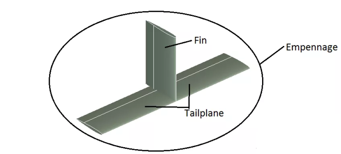
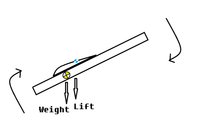
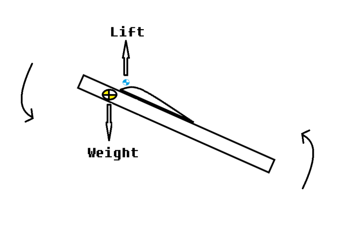
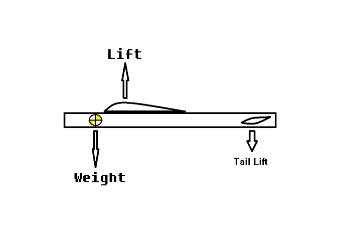
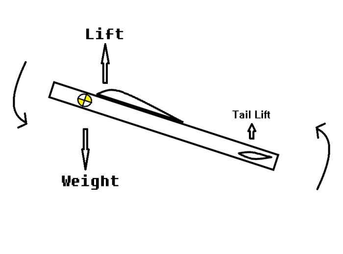
Fins are made to produce a weathercocking effect while still providing yaw control, and are simple. Tailplanes are made to delicately balance the wing’s down-pitching tendencies while providing pitch control, and are (relatively speaking) much more complicated.


Crooked Gains

Unlike fins, which need to be symmetrical, a tailplane also has the option of using a cambered section, like a wing. Unlike a wing, however, this has to be turned upside-down to provide the negative lift required to counter the wing’s pitching moment (see Tail Design 1 for why this is).

This is great for efficiency. While symmetrical aerofoils aren’t really bothered which way up they are, cambered aerofoils trade performance at 0-270º alpha (basically flying with your nose pointing towards the ground or even upside-down) to improve their performance at ‘normal’ flight angles. Nobody spends most of their flight with their aircraft upside-down, after all. The blood would rush to your head and you’d look like a tomato.

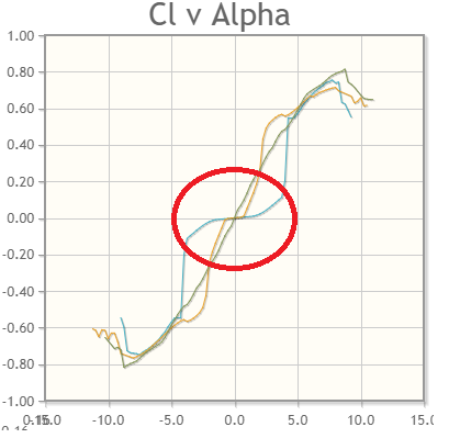
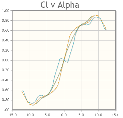
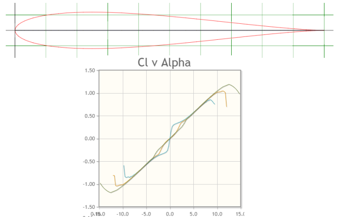
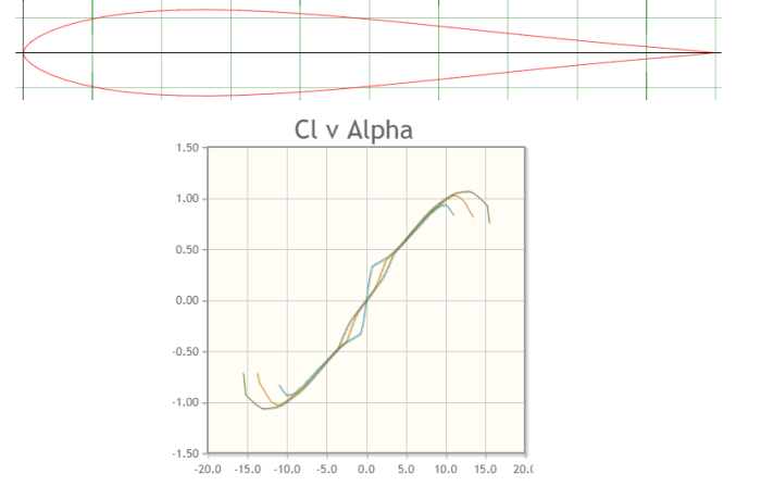
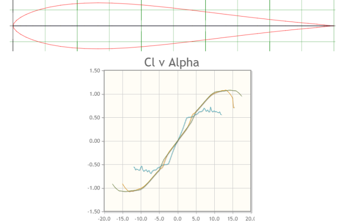
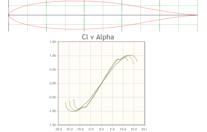
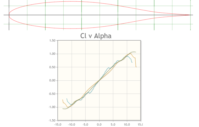
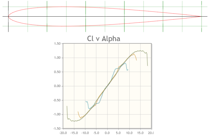
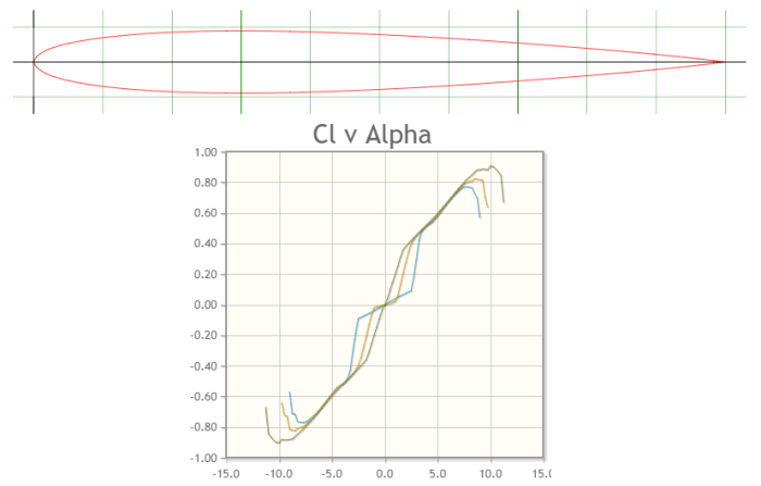
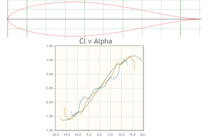
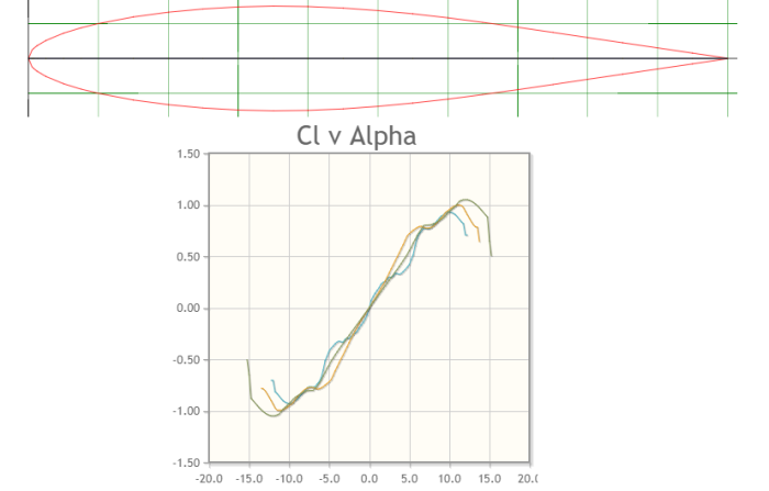
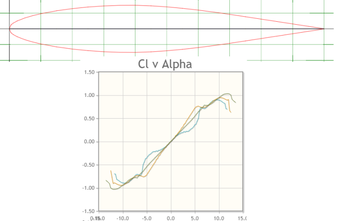
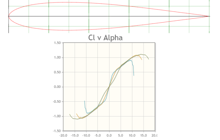
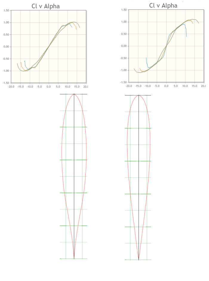
To illustrate this (not the tomatoes), see the below graphs:

Cl-Cd_vs_Alpha Wing-Tail
Lift/Drag ratio against angle of attack at Re=100,000


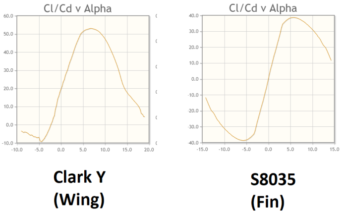
See how the lift-drag ratio is better with the Clark Y section at an angle of attack of about 7º? And see how the S8035 produces much more negative lift at an alpha of ~-5º?

The same applies to tailplanes. You want your tailplane to produce negative lift, and a cambered section will happily do so while producing less drag. Efficient!

(the ellipsis implies a catch)

However:

Wing V Tail
Lift Coefficient vs Angle of Attack for Clark Y and S8035 aerofoils at Re=100000


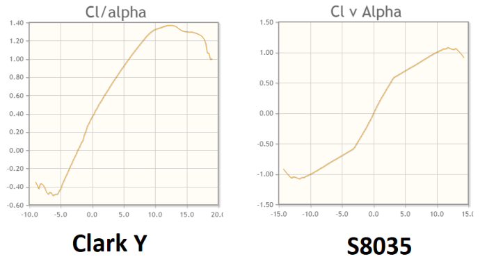
Across a wide range of angles of attack from up to down, we know pretty well how the S8035 is going to perform. It’s got a fairly linear lift response and performs just the same at both positive and negative angles of attack, so both designing and flying the thing will be simpler. That’s not to mention actually shaping an aerofoil shape at such small sizes. If we just go for the S8035 section, life will simply be easier across the board.


Shake that Empennage

I wasn’t expecting tailplane aerofoil selection to go that quickly, so we might as well incapacitate a pair of  avians with a single projectile.

As far as I’ve seen, most aircraft tend to go for strip rudders and elevators – that is, they span pretty much the whole lengths of their host sections. Sometimes the elevators have bits chopped out to prevent clashes with the rudder; sometimes it’s the other way around. This is a structural thing, and we can deal with it later.

Strip control surfaces can increase the risk of your servos getting damaged – if the end of the tailplane strikes the ground, for example, some of that force will be transmitted down the pushrods (the bits that connect your servos to your control surfaces) and could upset the multiple (often simple nylon) gears that allow the servo’s motor to get talking with that misplaced elevator. However, a projecting edge of balsa flown into the ground will simply snap, requiring an annoying repair job at fiddly scales. Servos and connecting pushrods also have a certain level of give in them, making those inevitable mishandling incidents a bit safer all round. Plus servos are cheap as chips to replace.

That just leaves us to figure out the chord of each control surface.

For the sake of mechanical simplicity, we’ll be tying our elevator and rudder chords together.


You know, there’s a very specific book by a very specific human person which I’m sure has this stuff written down… however it’s expensive and I don’t have it to hand. The internet is also being less helpful than usual in tracking down the relevant rules of thumb, though generally it looks like 20-25% is the norm for trainer-type models..

Going back to memory and… other sources… we’ll be setting our chords at 20%. This should provide us with sufficient control authority to get out of unpleasant situations without too much potential for dangerous over-controlling.

With the chord of the fin and tailplane already set at 0.14m:

Rudder Chord = ElevatorChord = 0.14 x 0.2 = 0.028

Let’s round that up to 0.03m.


Where That

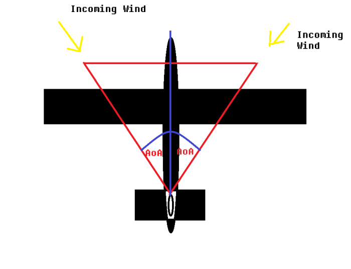
Right then, last thing to round up: where is the tail actually going?

This question will need to be answered so we can figure out how much fuselage/boom we’ll need to have supporting the tail. It’s more of a structural question at this point, but we might as well answer it now.

Up until this point, we’ve just been treating the tail moment as an abstract number. We’re going to give it some meaning.

A few posts ago we determined that the tail moment arm should be…

Ahem. It seems I have been leaving the “arm” part out of the term in previous posts. It seems I may have some editing to do.

Shit.

To clarify: moment is Force x Distance. It’s pretty important for levers. Moment arm, by comparison, is kind of another name for distance.

In fact, let’s just go back to saying “distance”.

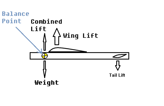
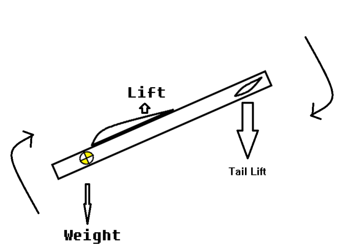
So, to recap: what I had been calling “tail moment” is the distance between the aircraft’s centre of gravity and the aerodynamic centre (see Basics of Wings Part 3) of the tail.

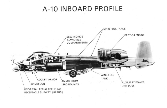
The centre of gravity, as a general rule of thumb, usually sits around 25-33% along the wing chord. Or it might be easier to say that the wing’s leading edge usually sits about 25-33% of its chord length ahead of the CG. It kind of depends how you want to think about it – the CG is the pivot, and the whole aircraft is built around it. Like how the A-10 is basically a plane built around a gun.

Fairchild Republic A-10A
“I am Heavy Weapons Guy… and this is my weapon” Wikipedia (https://upload.wikimedia.org/wikipedia/commons/d/da/A-10_Cross_Section.jpg)


Either way, we’ve already established that a forward CG makes for a more stable aircraft, so let’s go with 25%.

The aerodynamic centre of a symmetrical aerofoil will sit at it’s thickest point – this usually ends up being 25% along its length.

Tallying up our lengths:

Wing chord = 0.27m

Tail chord = 0.14m

Tail moment arm/Distance from CG to tail aerodynamic centre = 0.54m

CG = 25% along wing chord


CG vs Tail Pos
Well excuse me for not having a personal SolidWorks licence…

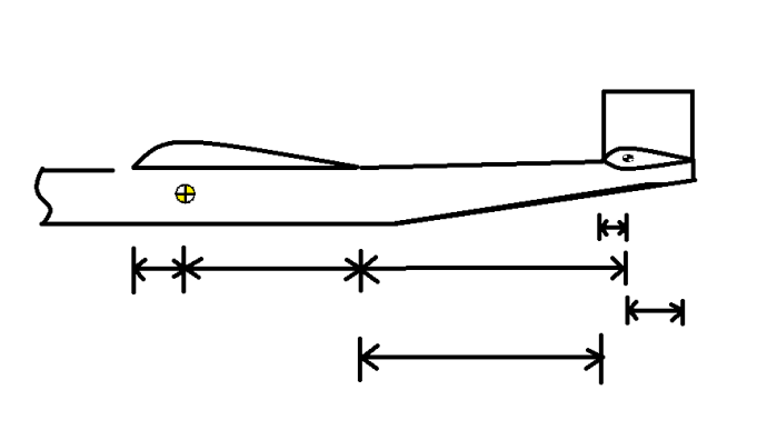
I really don’t know why I indicated so many potential measurement points here. The only interesting unknown here is how much fuselage lies between the wing’s trailing edge and the tail’s leading edge.

I mean, I say “interesting”… there’s a sharp thing at the front with magnets and shit that spins around hundreds of times a second and will happy fuck up whatever you feed it and scream for more. CG distancing? Tape measure-level junk. But it is kind of important. Botching the CG measurements can have results which can either be hilarious or appalling, depending on whether you’re flying a model or a full-scale aircraft. There’s a lot of stuff in aircraft that, if borked, will ruin not just your day but probably also someone else’s. It’s one of the greater reasons why aircraft are so damned expensive.

Ok, whatever. Numbers now.

Aaaaaaand I’ve put too much text between picture and maths, so now trying to write is difficult. Let’s post that picture again.

CG vs Tail Pos
Better… relatively speaking


Tail moment arm = Distance from CG to wing trailing edge + distance from wing TE to tail leading edge + distance from tail LE to tail aerodynamic centre

Rearranging for the variable we seek:

Distance from WTE to TLE = TMA – Distance from CG to WTE – distance from TLE to TAC

Plugging in the known value of tail moment arm:

Distance from WTE to TLE = 0.54 – Distance from CG to WTE – distance from TLE to TAC

Distance from CG to wing trailing edge = 0.75 x Wing Chord = 0.75 x 0.27 = 0.2

Distance from TLE to TAC = 0.25 x Tail Chord = 0.25 x 0.14 = 0.035m

Therefore:

Distance from wing trailing edge to tail leading edge = 0.54 – 0.2 – 0.035 = 0.305

Round that to 0.31m, and we have our number.


Well that only took freaking forever.

What’s next? I don’t know. Electronics? RC stuff? Structure? Unified theory of everything?

Answers will surely come in time. Probably also space, because reasons.

Assumptions all the way down

I waited for something, and something died

So I waited for nothing, and nothing arrived


OOOOOOOOOOOOOOOOHHHHHH


Still kicking.


Internet, you have no idea how much has been going on over the last few months. I can’t even remember most of it myself. Did any of it even happen? Are you still out there? Am I still here?

So! So so so. Why are we here? What are we doing?

Well, I might need a while to recalibrate. In the meantime, here’s a fun fact: nobody really knows why planes fly.

No joke! There are these things called the Navier-Stokes equations which explain viscous flow – specifically, how air flows around a wing (plus the rest of the aircraft). Thing is, they’re really, really difficult to solve – hell, they might not even have a general solution. Apparently you can simplify them down based on a series of assumptions and spam numbers at them until they spit out something sensible, but… well, there’s a $1 million bounty on figuring them out for good, and nobody’s spilled the beans just yet.

So in the meantime we’ve come up with (or fallen back on) a series of less accurate but easier to work with formulae which are good enough. As the boundaries of human ignorance are inexorably rolled back, these formulae will likely shift and change and improve.

Still, kind of scary, huh? The physics that govern flight are still an unknown, so we’re running on a complex structure of deductions based on supposedly empirical data which itself is based on a series of assumptions we may never be able to prove.

Those of you who know me in meatspace might sense a tangent developing. And your senses would be right.

Just what can we know, anyway?

I mean, we fly on the assumption that the laws of physics as we know them will hold well enough to see us through. We haven’t been presented with any evidence that the relevant laws of physics would flaunt our understanding in such a dramatic way that aircraft will stop flying and fall out of the sky. But as Asimov’s Multivac stated in The Last Question:

“INSUFFICIENT DATA FOR MEANINGFUL ANSWER.”

By the way, if you haven’t read The Last Question: for the love of God, open a new tab and read the thing start to finish. It won’t take long, and your mind will be blown like the guy from Scanners. Unless you have no imagination, or have heard or conceived of something similar before… or if I haven’t taken sufficient account of the massive diversity of human perception and it just doesn’t really do anything for you. I know people for whom the Beatles do nothing, which I can’t for the life of me understand… I can only respect their abilities for form valid value judgements in a state of dazed befuddlement.

Point is this: we base our entire perspective on the assumption that our senses and cognitive abilities will provide an accurate picture of reality – something we know can be wrong. Magic tricks rely on simple but finely-controlled distraction and slight of hand, and yet are quite capable of duping us all. How do you know you’re not dreaming that you’re reading this text, and you won’t wake up as an unusually-intelligent butterfly with a major identity crisis?

Descartes pointed out that if I think, then I am… but note that only applies to the first person. I only know that I am alive, and nothing more. This makes solipsism a tempting refuge… but I refuse on principle to go along with that, because it just seems ridiculous. Perhaps I am the ridiculous. Perhaps time will prove me right. Or wrong. Who knows? I certainly don’t.

We’ve established that we can’t really know much of anything (this may itself be wrong)… so what now?

We assume, that’s what. Sure, it makes an ass of you and me, but damn it, it’s the only thing we can do to progress.

We start with something simple.

You see an apple falling from a tree. Do all the apples fall in the same direction and with the same acceleration? If you picked up an apple in one hand and a bucket in the other, would they both fall at the same speed if you dropped them? Are the answers to these questions reliably identical?

Now take one of the apples and throw it, making sure to record its trajectory. What is the shape of its flight? Does it fall down again? How much distance does it cover during its journey? How long does it stay aloft?

Repeat the apple throwing multiple times, then try throwing it at different angles. How do the answers to the initial questions change? Now repeat the experiment with a bunch of different objects.

You’ve started to lay the framework for a basic understanding of Newtonian physics applied to solid objects. Next, we’ll try fluid dynamics.

Run a bath. Get into the bath. Does the water level change, and by how much? Now get out of the bath. Does the water level return to its original state? Run your hand through the water with your palm facing the direction of movement. What did you feel? What is the surface of the water doing? Now repeat, but this time with your palm facing perpendicular to the direction of travel. Was that easier, or harder? Has the water behaved any differently?

Now pop the kettle on and brew yourself a mug of boiling water. It’s hot, isn’t it? Now throw it into the bath. Is the bath boiling hot?

Now pick up a piece of paper by two corners and blow over the top. Does it rise?

It all comes down to testing stuff over and over again until you think you’ve got a working model. You acknowledge that someone might come along with a more convincing explanation… but then again, they may not. Now ask yourself: can I use this model I have created to solve a problem or just make something exciting?

And I guess that’s engineering in a nutshell: taking an idea about how the universe works and applying it to solve problems, and learning and improving it if it doesn’t behave according to expectations.


OK, bizarre philosophical rant over. Normal service to resume… well, probably much less than 6 months from now. But who knows?

Tail Design 4: *Jaws music*

Hello fellow internet creatures. Today we will finally be finishing off (sort of) the aerodynamic side of the tail.

I mean, that was the plan, but then I got distracted by unending choices of aerofoils and did I mention life is busy?

If memory serves, we’ll need to cover the following:

  • The aerofoils we’ll be using for the tail surfaces
  • The dimensions of the flappy bits (aka rudder and elevator)
  • Precisely where the tail is going to sit vs the wing
  • … I think that’s it

Funnily enough, we’ll just be covering the aerofoil we need for the fin in this post… and that’s it.

So after a looooooong break during which life has been packed with great volumes of jam, I ask you, dear reader:

Won’t you share this jam with me?


Tail Aerofoils (Taerofoils? Aerotails?)

A very long time ago, we covered the aerofoils we’ll be using for the wing.

… And golly flipping gee, that got out of hand. We will try to avoid that level of text wall (I wrote this sentence about a month ago, and I don’t think I followed it to the letter).

K, right, onwards:

We want different things from our tailerfoil. Unlike wingerfoils, our aerotail will need to… you know what, these experimental hypothetical portmanteaus are messing with my thinking typing brain, and the feels part of my brain is becoming upset. Let’s move on.

Let’s start simple, and start on picking our fin aerofoil. What do we want?

  • The fin aerofoil must be symmetrical. Otherwise it would constantly be trying to pull the tail off to one side, which would make our aircraft want to turn all the time and would generally make it much more draggy and horrible to fly.
  • It mustn’t be too draggy, though since it’s much smaller than the wing, this isn’t such a big issue.
  • It must behave in a relatively predictable way (we can’t have it wagging our aircraft around and stalling suddenly).
  • The shape must be easy to build, and not have be so thin as to be fragile.
Bubble
Lavender thought clouds are not an optimal aerofoil shape.

There are some other bits we might want to pay heed to like pitching moments at a more advanced level, but for now, let’s just get on with it.


I can’t think of a pun linking stalling and fins.

If I haven’t already mentioned before (and I can’t quite be bothered to check properly): it’s probably much harder to stall a fin than, say, a wing. You may remember how the angle of attack is the angle of the incoming air vs the aerofoil.

The thing is, the fin is an aerofoil sat on its side – so its angle of attack will be the same whether your nose is pointing up or pointing down. All the fin really cares about is the air coming in from left or right.

Fin AoA
This drawing will definitely make things clearer and makes perfect sense.

You might be able to stall it if you were yawing really fast, but since it’s pretty much the back end of a weathervane… it would be quite difficult. With the aircraft spinning round in a circle, one of the wings would be travelling faster than the other – you would likely cause the aircraft to enter a spin, which would present a very serious (and potentially unrecoverable) problem.

In summary: stalling fins is hard and you would cause bigger problems by trying to do so.


Flat plank? More like… no.

In truth, for a model of this size we could always settle for a flat plank which we could just sand the edges off… but this would be inelegant, and for a model of this size… I would never be happy with it.

Green Plank
Artist’s impression of flat plank-type aerofoil. You can tell an artist did this, because the plank is green.

Based on internet searching and general personal experience, most models use relatively thin symmetrical NACA and Eppler aerofoils if they’re not just planks.

With this context in mind, we might as well get on.

Warning: maths incoming.


RRRREEEEEEEEEEEE

Well, the next stage might as well be figuring out what kind of Reynolds number our tail will be flying at. We’ve already determined the tail should be symmetrical which excludes a huge swathe of aerofoils.

To refresh: Reynolds numbers are basically the ratio of the aircraft’s inertia to the viscosity of air. As far as we’re concerned, bigger Reynolds number = better performance.

Remember the formula from way back?

Reynolds Number = Density of Air x Airspeed x Chord Length ÷ Kinematic Viscosity of Air

And since we probably won’t be doing any extreme flying in extreme places, we can simplify:

Re = 1.225 x Airspeed x Chord Length ÷ 0.00001456 = Airspeed x Chord Length x 84130

And from our earlier posts, we already know that:

  • Chord Length = Fin Chord = 0.14m
  • Airspeed = Cruise Speed = 8.2m/s

So Re= 8.2 x 0.14 x 84130 ≈ 95000

So if we aim for aerofoils that behave well at Re=100000, we should be good. Just to be on the safe side, we’ll be keeping an eye on behaviour at Re=50000 and Re=200000 – this will mean we can spot any nasty behaviour around stall speed and… racing speed?


Picking Our Poison

Oh, now here’s something interesting:

This right here is a gaggle of graphs exploring the behaviour of the LWK 80-100 symmetrical aerofoil. It has a pretty high lift-to-drag ratio, which is great, but…. see how the lift just seems to flatten out between about -4 to +4 angle of attack?

Weird Tailerfoil Behaviour Highlighted

This aerofoil seems to have a dead zone – especially at Re=50000 (blue line – chances are the worst-behaving line will be from when the aerofoil is travelling the slowest). This will mean that changes of angle of attack between -4 and +4 degrees won’t change the lift provided, which is… well, imagine if you couldn’t walk in a straight line and had to keep correcting your course in a constant and imprecise zigzag. Trying to walk through a busy street would become even more stressful than usual (seriously, who put these people in the way?).

Now imagine trying to land an aircraft that won’t fly straight. That’s stressful.

Bottom line is: nope. This aerofoil is a no-go, which serves as a very useful example of what we want to avoid. Maximum lift-to-drag ratio is not the be-all and end-all!

Also, “zigzag” is a good word which I should use more often.

NEXT!

Oh hey, this behaviour is actually pretty widespread.

SCIENCE!

Looking at many of the graphs, it seems that some symmetrical aerofoils start behaving completely in reverse around these shallow angles of attack – their lift decreases with a higher angle of attack, before snapping back to normal past a critical point.

Tailerfoil Lift Reversal
I mean… what?


Spline Ho

There are a lot of aerofoils out there, any many seem to be quite samey on the whole lift/drag front. So in an unprecedented (for me) (well, at least since leaving university) effort, I’m going to compare the shapes against their lift-drag graphs.

You’re welcome, internet.

12% JOUKOWSKI
12% JOUKOWSKI

I saw a lot of this sort of behaviour – sharp lift response at mild angles of attack, tailing off towards the mids and extremes. The aerofoil’s behaviour seems unusually consistent across different angles of attack, with only the stall angles and slow-speed lift response varying significantly. Speaking of stall angles – the stall occurs at roughly 9°, which isn’t the best on test.

A simple aerofoil shape, curving off to a sharp trailing edge – this wouldn’t be too hard to trace or produce. It does get pretty thin at the back, though…


E168 (12.45%)
E168 (12.45%)

This aerofoil behaves relatively similarly to the one above (note the different scaling on the two graphs), but keeps flying at slightly steeper stall angles at all speed ranges.

From a mechanical standpoint, the taper is less pronounced, and thus would be less fragile.


E169 (14.4%)
E169 (14.4%)

This slightly chubbier sibling of the E168 aerofoil seems to struggle with slow-speed flight at low speeds, though it does appear to fly better at higher speeds, with higher stall angles and a flatter response at the extremes that would give greater warning of an impending stall.

A marginal increase in thickness does benefit the trailing edge, though the slow-flight performance means this will only serve as an example of what to avoid where possible.


EPPLER 520
EPPLER 520

For our purposes, this is beautiful. The change in lift with angle of attack is almost linear, and seems to behave almost identically across all three speed ranges. Stall angle of about 12° is average, as is the warning of stalls. The maximum lift doesn’t quite match the other aerofoils we’ve been looking at, but that’s not the end of the world.

Aerodynamically, this is fantastic. Geometrically… it’s not the easiest shape in the world to trace, and that taper… yeesh.


FX 71-L-150-20
FX 71-L-150-20

This… jiggly. Am suspicious.

The generally linear lift response and reasonable stall angles don’t quite offset my suspicion of the noisy slow-flight behaviour. Plus warning of the stall doesn’t seem to be in abundance.

Also taper. It looks like it would break if we were to poke it.


GOE 410
GOE 410

Nice easy shape to make, and pretty great mid to high-speed performance… but slow-speed performance just isn’t up to par.

This is a shame, because it looks nice to build and much less worrisome at the back.


NACA 0009
NACA 0009

I think I tried to use this aerofoil back in university… and in truth, I can’t quite think why. The lift response across all speed ranges gets squashed in the middle, the stall angle (and warning of stall) is “meh” all over, and the maximum lift is way lower than the other aerofoils.

It does look quite easy to trace and build, with a shallow taper producing a relatively strong trailing edge.


NACA 63(3)-018
NACA 63(3)-018

I don’t know why I put this aerofoil in this list.

What is even going on?


NACA 63-015A
NACA 63-015A

Unfortunately the slow-speed lift response is a bit weird on this one, though it does seem to behave better at higher speeds. Stall angels are reasonably good though.

It also looks nice and easy to build, with a strong trailing edge. You might even be able to install a servo directly into the fin, should you so desire.


NACA 642-015A
NACA 642-015A

Same deal as above… but possibly slightly worse performance.


S8035 for RC aerobatic 14% thick

Generally nice performance here across all speed ranges, though the stall angle at low speeds is a little shallow. Lift response isn’t as linear as it could be, but it’s certainly not bad.

The shape appears to be reasonably easy to build, with a strong trailing edge.

Note: pretty much all my airfoil data (including the set below) is available from airfoiltools.com. It’s not great at giving recommendations, but if you know what you want from your aerofoils or know where to look for advice… this is likely the best source on the internet.


(Fin)al Round (see it’s funny because… oh, who am I kidding? Maybe this is why I always take so long to get new posts out.)

I think we’ve got it down to two aerofoils: the Eppler 520 vs the S8035 section. At this point, it’s a matter of aerodynamics vs geometry. The Eppler aerofoil is more consistent and better-behaved across all three flight modes… but would be a bloody nuisance to cut and transport with that super-thin trailing edge.

Let’s give them one last comparison…

Tailoff
E520 on left; S8035 on right


You know what? Executive decision time. This is a basic trainer, and if we do anything extreme with it, we are only asking for trouble. Let’s just make it easy to build and see how it goes.

S8035 it is!

Now, where were we?


Two Weeks Later…

Ok, no. This is getting stupid, and I will never get this post out the door if I try to finish everything in one go.

Whatever. Now you have a basic grip on how to choose a fin aerofoil.

We’ve still got to cover:

  • How big the rudder is going to be
  • The tailplane aerofoil (urgh)
  • How big the elevator is going to be
  • Why you should always stay hydrated
  • Where the tail is going to sit (although this is kind of a structural thing, so we might just deal with it later)
  • What would happen if you threw a jellyfish in a microwave


Well, I suppose I should go find something else to make me miserable. Wish me luck!

Tail Design 3: Fin Soup

So in the last post, we set the design of the tailplane. Because of the fin’s relative simplicity in function and design, we decided to slave much of its design to that of the tailplane.

For our purposes, we can pretty much just slap the fin on top and be done with it – same moment; same chord. Even the maths we need for shaping the fin is pretty much the same as with the tailplane.

Bask in that simplicity for however long you deem appropriate.

459142a-i1-0
Apparently this basking shark was so good at basking that they named it after that singular characteristic. Also for being a shark.

The size and location of the fin can be determined by the Fin Volume Coefficient. Remember our friend* the Tail Volume Coefficient?

Tail Volume Coefficient = (Tailplane Area x Tail Moment) ÷ (Wing Area x Wing Chord)

Replace anything that says “Tail” with “Fin”, and switch “Wing Chord” for “Wing Span”, and you’re good to go.

Fin Volume Coefficient = (Fin Area x Fin Moment) ÷ (Wing Area x Wing Span)

And… since we’ve already decided to just slap the fin on the tailplane, the fin moment is the same as the tail moment. We therefore have only two unknowns: Fin Volume Coefficient and Fin Area. We’re actually looking for Fin Area, so we really only need the Fin Volume Coefficient after all.

Aww yeah. Cue internet.

I’m seeing typical values of 0.02-0.04 for this type. It was a bit trickier finding firm (and relevant) sources than unusual, so let’s settle with the middle value and go for 0.03.

Fin Volume Coefficient = 0.03

You might have noticed that this number is much, much smaller than the tail volume coefficient Or you might not have done, and that is ok. This is a judgement-free place of learning. Shame does not apply here.

Thing is, the tailplane is constantly wrestling with the wing in an effort to keep the nose up (see stability posts for explanations of why). The fin is pretty much there to give the aircraft a weathercocking tendency to keep it flying straight. The only thing it has to counterbalance is the (much smaller) weathercocking effects of the wings.

How to explain… I guess we should look at the weathervane. You know how they tend to have that tail bit at the back?

xxx_7779_1351108639_1
Or… you know… a cat.

That’s just there to cause a lot of drag, which will force the front to face into wind. If that tail wasn’t there, the arrow part at the front of the weathervane would be causing the most drag, basically causing it to become the new tail. Congrats; your weathervane is working backwards. Collect your dunce hat at the conclusion of this post**.

Same idea for the wings. If there wasn’t a fin, the wing would start acting like a fin and push the aircraft to follow the wind. Since aircraft need to be flying faster than the surrounding air to… you know, fly… as far as the wings are concerned, they will always be facing the wind. The wings will try to weathercock to be behind the centre of gravity, which means they will always be trying to turn off-course. This would be a terrible nuisance and also very dangerous.

Since wings tend to be pretty thin, they don’t present much of a frontal area for the wind to grab onto and forcibly yaw. This means the fin doesn’t have to fight very hard, especially as it’s placed well back from the centre of gravity (this is exactly what Fin Moment is). Thus, you can make the fin a lot smaller than the tailplane.


Anyhoo, let’s get back on track and plug in our values into the Fin Volume Coefficient formula.

0.03 = (Fin Area x 0.54) ÷ (1.5 x 0.27 x 1.5)

Remember, Wing Area = Wing Chord x Wing Span. Working the numbers down:

0.03 = Fin Area x (0.54 ÷ 0.61) –> 0.03 = 0.89 x Fin Area

And rearranging:

Fin Area = 0.03 ÷ 0.89

Fin Area = 0.034m^2


Now we know how large the fin has to be, we have to set its shape. Based on the previous post, we have to look up typical aspect ratios of fins and stuff, right?

Nope! Because we’re slaving the fin design to the tailplane (mostly out of laziness), we’ll just use the same chord, i.e.

Fin Chord = Tail Chord –> Fin Chord = 0.14m

And since Fin Area = Fin Chord x Fin Span:

Fin Span = Fin Area ÷ Fin Chord

Fin Span = 0.034 ÷ 0.14

Fin Span = 0.24m


We done.


Well, mostly. We still need to give the tail surfaces aerofoils (smaller aircraft could settle for just using planks, but we’d need some pretty big planks for our purposes), and there’s the detail of where exactly the tail is going to sit vs the wing (the tail/fin moments were distances set vs the centre of gravity, but we don’t know where exactly that is yet).

Otherwise… yeah. Good job?


And now to post the thing that has been running circles through my brain the whole time I’ve been writing this. Because I can.


*”Friend” being a relative term. A simple formula, being a non-physical concept, has no capacity for friendship, though it might be perceived as being a little less hostile than, for instance, being asked to derive the Bernoulli formula for lift. Ask your friends what a “friend” is. If you have no friends, I would suggest consulting the denizens of the internet. It’s probably best you don’t ask them to be your friends though. Internet people can be weird. Then again, physical people can be weird.

**This was in jest. You are a wonderful and intelligent person. Otherwise you wouldn’t be on this blog. And now we both feel better.

Tail Design 2: Empennages and Animals are Free

And now we actually get the tail bits designed! I totally just realised the last post should have been labelled as tail theory or something. That whole thing kind of ran away with itself. Henceforth, things should be a little more focused.

Thus: forwards, to the bits at the back!


Seesaws, how do they work?

Given the relative simplicity of the design of the fin, we’ll be leaving it aside until we have the tailplane sorted out. Longitudinal stability can be a right pain sometimes, but we can’t fly nothing until we gots it sorted.

Remember from the last post how the tailplane acts as a counterbalance to the wing’s tendency to pitch down? Like a seesaw, there are two key factors in determining how effective that counterbalancing can be: how much brute force the tail can generate, and how far it is away from the balancing point. In the case of an aircraft, the centre of gravity is that balancing point.

physics-activity-2
Something has clearly gone wrong here. Discovery (http://r.ddmcdn.com/s_f/o_1/DSC/uploads/2014/07/physics-activity-2.jpg)
combined-balance
The CG is the pivot here, the girl is the wing except backwards… erm… oh bugger it, if you’ve been reading from the start and still don’t get it, you’re probably not going to.

Now, calculating exactly how much counterbalancing force the tailplane can generate involves the same long, drawn-out process we used for the wing. This idea bores me, and we have a perfectly good shortcut that will suit us just fine. It basically comes down to this:

  • The tailplane is there to work against the pitching-down tendency of the wing
  • Logically, you’d think a big wing would need a big tail to compensate
  • Instead of calculating the exact downforce generated by the tailplane, why not just slave the size of the tail to the size of the wing?

With this in mind, we’ll be using the nifty formula for the Tail volume coefficient. It basically allows us to take the size of the wing, and use that information to determine how big and how far back our tailplane should be.

Tail Volume Coefficient = (Tailplane Area x Tail Moment) ÷ (Wing Area x Wing Chord)

Tail Moment is the distance of the tailplane’s aerodynamic centre from the aircraft’s centre of gravity. This will come in handy when we start designing the fuselage, but for now will just be a variable to solve.


Breaking Wing Area into its constituent parts, chord and span:

TVC = (Tailplane Area x Tail Moment) ÷ (Wing Span x Wing Chord x Wing Chord)

Or more concisely:

TVC = (Tailplane Area x Tail Moment) ÷ (Wing Span x Wing Chord^2)

Plugging our values for Wing Chord and Wing Span (see Wing Design: Part 4):

TVC = (Tailplane Area x Tail Moment) ÷ (0.27 x 0.27 x 1.5)

Tail Volume Coefficient = (Tailplane Area x Tail Moment) ÷ 0.11

To clarify, I rounded up pretty roughly. We’re only dealing with the initial design here, so we’ll be fine with this.


So we now have three unknowns: Tail Volume Coefficient, Tailplane Area, and Tail Moment. Tail volume coefficients are basically just ratios, so picking within a rough range should give us the answer we need. Too low, and the tailplane won’t have enough authority to overcome the pitching moments from the wing. Too high, and our tailplane will be big, heavy, and will be so stable it will end up fighting us when we actually want to change pitch. Fortunately, there are a whole bunch of books and internet sources with just the range we need, and generally speaking, they say that the Tail Volume Coefficient should range from 0.35-0.45. Since this is only a simple model meant to be flown by pretty much anyone, let’s just go for the middle value, and say:

Tail Volume Coefficient = 0.4

Plugging this back into the formula:

0.4 = (Tailplane Area x Tail Moment) ÷ 0.11

And rearranging:

Tailplane Area x Tail Moment = 0.4 x 0.11

Tailplane Area x Tail Moment = 0.044

Success!

dexter
Yes, I had a childhood.

We’re now left with the only two numbers we actually care about.

So… what now? Find out next time on Let’s see. We have two unknowns and a numerical relationship between them. We could do pretty much anything here. For instance: feeling lanky? Let’s throw that tail 2m back. Tail Area will be 0.022m^2. Fancy something more compact? Let’s try 10cm back – Tail Area will be 0.44m^2. The tail closer to the CG is 20 times as large as the one that’s planted way back. In all likelihood, it would also occupy the same space as the wing, which is clearly impossible. I mean, unless your engineering skills are native to Ry’lyeh, in which case… why the hell are you reading this blog?

We’ve established a relationship between Tailplane Area and Tail Moment; if we set one, we also set the other. But which factor do we want to set? And if we can pick any value, where do we even start?

This presents a particularly interesting question: what do you do when you have literally infinite options to choose from? Indeed, taken out of the aircraft design context and applied generally, this question has a dizzyingly-wide swathe of philosophical implications. We are indeed condemned to be free.

If, like me, that statement fills you with existential dread, then fear not!


FREEDOM IS SLAVERY [sort of]

There are a few factors which narrow our options down. A key part of engineering is overcoming challenges with a limited range of approaches.

Consider the following factors in favour of a shorter fuselage with a larger tail:

Structural

  • A small tail will require a long fuselage; a long fuselage is a weaker and heavier fuselage which will break easily.
  • A smaller tail could be more fragile.

Practical

  • Airfoil shapes are not the easiest things in the world to build. Take it from me: small tail surfaces can be a bloody nuisance to shape. Having a larger tail would make it easier to build the tail from constituent pre-shaped parts, making a proper aerofoil shape much easier to create
  • A long fuselage could make transporting and storing the model more difficult, as it would take up more space.
  • Your control surfaces would be further away from your servos (the bits that move the control surfaces), so you’d need long control cables to connect your servo arms to your control surfaces; this would increase slop and could lead to nasty aerodynamic complications (look up flutter).
  • Landings would also be more tricky, as that long fuselage would make tail strikes more likely.

Aerodynamic

  • A small tail will reduce the Reynolds numbers of the air flowing over the tail. This tends to reduce performance across the board, though in our situation it isn’t critical.
  • A large, close-in tail would be better able to take advantage of propwash, where fast-moving air accelerated by the propellor passes through the area occupied by the tail. This give the elevator and rudder extra bite at low speeds, improving control in a particularly vulnerable area in the flight envelope.

And those in favour of a long fuselage with a short tail:

Structural

  • A short fuselage will require a large tail, which will be heavier than a long fuselage and a short tail. This could make balancing the aircraft slightly trickier.

Practical

  • Assuming we’re fabricating the model from balsa: if built small enough, tail surfaces can actually be sanded into shape from a single sheet of balsa. A tail which is slightly too large for this will need to be assembled from individual parts, all of which will need sanding to shape. This can be a bloody nuisance.

Aerodynamic

  • A large, close-in tail could lead to unexpected aerodynamic interactions which could introduce funky behaviour and reduce efficiency. Fluid dynamics is complicated like that.

There’s probably a heap of factors that I’ve missed, but you get the gist of it.


IGNORANCE IS STRENGTH [well…]

So, odds are we’ll probably want a shorter fuselage with a larger tail. But that still doesn’t really give us any figures to work with.

So! We’ll do what any engineer worth their salt does, and cheat a bit. Cue internet.

General searching reveals a commonly-accepted figure: that the Tail Area is usually 15-20% of the wing area. Let’s go large and settle on 20% – this is a trainer after all, and we’ll want the extra stability.


Tail Area = Wing Area x 0.2 –> Tail Area = Wing Span x Wing Chord x 0.2

Tail Area = 1.5 x 0.27 x 0.2

Tail Area = 0.081m^2

Tailplane Area x Tail Moment = 0.044 –> Tail Moment = 0.044 ÷ Tail Area

Tail Moment = 0.044 ÷ 0.081

Tail Moment = 0.54m

WOO!


Now, the Tail Moment figure will come into its own later. For now, we’ll get along with setting the shape of the tailplane – which pretty much comes down to setting an aspect ratio and running with it. Cue internet again.

K, so it looks like the norm is 4-5. Since a square tail is a stronger tail, let’s go low and aim for 4. It won’t be as efficient, but it will be more likely to survive the tougher knocks of life. Since the tailplane chord is increased as a result, we also get a bit of a boost to Reynolds flow, which is always handy.


Tail Aspect Ratio = 4

Tail Aspect Ratio = Tail Span ÷ Tail Chord –> Tail Span ÷ Tail Chord = 4

Since we have two unknowns, this isn’t of much use to us. However, with some mathematical poking:

Tail Span = 4 x Tail Chord

We’ve made one of the unknowns a function of the other. Recalling our Tail Area:

Tail Area = Tail Chord x Tail Span = 0.081

We just plug our former formula into our latter one:

Tail Chord x (4 x Tail Chord) = 0.081

Cleaning this up:

Tail Chord^2 = 0.020

So therefore:

Tail Chord = √0.020

Tail Chord = 0.14m

And plugging this back into our rearranged aspect ratio formula:

Tail Span = 4 x Wing Chord = 4 x 0.14

Tail Span = 0.56m


So now we know:

  • How big the taiplane is going to be
  • Where it’s going to sit vs the CG (not much use to us right now, but will come in handy later)
  • What shape the tailplane is going to be

To complete the empennage design, we need to figure out:

  • How tall our fin is going to be (we’ll just slave fin chord to tailplane chord for the sake of simplicity)
  • What aerofoils we’ll be giving our tail surfaces


WAR IS PEA- hang on…

I have just picked this post up after… what, a month? Three? I’ve actually starting building a new plane out of foamboard in the interlude. Progress has been stymied by the fact that my foamboard sheet is too small to build the wing with. Also laziness.

wp-1483134990134.jpg
Absolutely flawless.

What else? Unexpected change in circumstances. Very exciting. Yes. Much disruption. Would have thrown fin design in here, but then the post wouldn’t have gotten out for another few months while I procrastinated about the size of this post.

More posts in future. When? The future. I have sort of exhausted the word “soon”.

Oh yeah, one last thing – it’s past midnight and I couldn’t quite be bothered to do my usual thing of multiple re-reads with a fine-toothed eyeball. Mistakes may come back to bite, but things look pretty ok. There’s an age-old rule of thumb with flying: “If it looks right, it’ll fly right”. This won’t help with bad CG placement (believe me, I know), but in these initial stages, we can afford to be a bit loose.

Until next time. In the future. By which time this post will be in the past. Spooky.


Tail Design 1: Swiggity Swooty

Sadly we’re not at the level of technology where the doctors could go all Deus Ex and replace my boring biological hand with an awesome robot one, so they had to settle with merely mostly fixing it. Alas. At least I have you, blog. And you, ukulele. And you, lamp. God bless you, lamp.

Oh. I have another ukulele now… wait, how long have I been trying to write this post?

K, since we’re done with wings for now, we need to figure out the other important bit: how to design the tail?

These bits at the back give us most of the control over our aircraft. If we dialled enough dihedral into the wings, we could actually ditch our ailerons entirely and just use the tail surfaces to control direction.

As we discussed way back two years ago, the tail (or empennage, depending on how french you’re feeling) is formed of two pieces: the fin and the tailplane.

Tail

The fin is like a weathercock that keeps you heading directly into the wind, which stops you from being blown off course. Attached to the fin is the rudder, which gives us directional control. There’s relatively little complexity to the design or function of the fin, so we can rustle up a good design in a cinch. Mostly its placement and shape tend to be slaved to the design of the tailplane.

The tailplane is a counterbalance to the wing’s tendency to pitch downwards. It enables us to fly in a direction that isn’t just down. Attached to the tailplane is the elevator, which gives us control over our pitch (up and down) angle. While the elevator is simple enough to design once we have its host surface sorted out, the tailplane is more complex in function and the fin, and the rest of this post will be devoted to explaining it.


NOPE NOPE NOPE

So I’ve spent the last few months on and mostly off trying to get an explanation written out as to why the taiplane is important. So then I started trying to explain how the centre of pressure changes with angle of attack, which led me into attempting to explain pitch stability again, which of course led into HOW IS THIS MY LIFE

Ahem. This is a different and complicated kettle of fish which is best avoided for now.

SO! Below, I present my horrifyingly over-simplified (but still kind of useful) explanation on why we need a tailplane. Aerospace engineers: avert your eyes, lest ye be struck down with the stupid.

… Oh hey, it’s not actually all that terrible.

yay

Uncomfortable Balance

  • If the aircraft’s weight and lift are in the same spot, the aircraft is balanced and we’re all good.
balance
This is fine.
  • However, this is pretty much impossible to achieve in practice, because the point at which that lift is produced moves backwards and forwards.
  • Centre of lift shifts forward when you pitch up, and backwards when you pitch down.

Oh No

  • If the centre of lift shifts in front of the centre of gravity, your aircraft will always want to pitch up.
unstable-notail
Everything changed when the Fire Nation attacked
  • The further the wing pitches up, the further that centre of lift is going to move forward.
  • BUT wings can only produce lift up to certain pointy-uppy angles (angle of attack).
  • Past a certain point, the lift will reduce and the wing will stop flying.
  • This is generally regarded as being quite bad.

Also Oh No (but slightly less so)

  • Push the nose down, and centre of lift will shift backwards.
  • However, because the wing is pointing down, it’s now generating negative lift.
  • This pulls the tail down, and the nose up, until the lift and the centre of gravity and centre of lift are occupying the same spot.

    stable-notail
    But then someone found a hosepipe
  • This returns us to this place:
balance
Who needs the Avatar, anyway?
  • However, because we’re still pitching upwards, there’s going to be some overshoot, where the centre of lift is going to shift just that little bit further forwards than the centre of gravity.
unstable-notail
Then Gary gave the Fire Nation a recipe for napalm


Back to square one.

So…

While it would be nice to fly straight and level all the time, this is clearly impossible. This being the real world, with… you know, wind and stuff… there are inevitably going to be disturbances to our perfect flight. We need stability, and we need control.

We’ll do this by moving the centre of gravity forwards. The result?

unstable-notail-cgplus
OH SNAP

When the aircraft has its nose pushed up, the centre of lift will move further forwards… and push the nose down – up to a certain point. You could actually push the centre of gravity so far forwards that the wing will stall before the centre of lift moves in front.

Now you may be thinking something along the lines of ‘but wait, won’t that mean the plane will always want to fly into the ground?’ Further, you might be thinking ‘flying into the ground is a bad thing.’

Correct on both counts, imaginary freakishly idealised reader. However, we have achieved a key goal: stability. The plane will want to return to an equilibrium point – a specific angle of attack. However, this angle will always be negative, meaning it will always want to point groundwards.

We have achieved a stable aircraft, but not a balanced one. And we still have no pitch control.

This is why we need a tailplane – because the only way to achieve a stable flight without one will have us flying into the ground all the time*.

Here’s how they do it in the big wide world:

w-tailplane
Avatar state! Yip yip!

Now this is where it’s at (please excuse my less-than excellent MS Paint skills).

With the centre of gravity some way in front of the wing’s aerodynamic centre (the point around which the centre of lift will change – see Basics of Wings part 3), the lift being produced by the wings will want to push the nose down. However, the tailplane (which is pointing slightly downwards) will be pushing the tail downwards, and thus the nose upwards. Net effect? Nothing. Plane stays flying straight and level.

If we push the nose up, the wing lift will increase, pushing the nose back down, and the tail… let’s call it anti-lift will decrease – reducing the force which is holding the tail down, thus allowing the nose to sink. Push the nose high enough and the tail will start producing positive lift, which will really start pushing that tail back up. Combined effect? Nose falls back down.

w-tailplane-up
Dive, dive, dive

If we push the nose down, the tail anti-lift will increase, which will want to push the nose back up even more. The wing’s lift will have moved further back, which be unhelpful – however, it’s also been reduced, and as long as the tail is far enough back (we can ensure this with maths which we will avoid), will be unable to overcome the greater lever action of the tail. Back to the seesaw analogy: think big man standing close to centre of seesaw vs child at end of seesaw. That child is going to have more leverage.

w-tailplane-down

NOTE: you might be wondering why the wing isn’t generating negative lift, like the tailplane would if pointed down. Most wings use aerofoils which keep generating lift, even when pointing slightly downwards. Our Clark-Y aerofoil won’t start generating negative lift until it passes about -2.5 degrees angle of attack.

Throw an elevator in, and you can fine-tune the anti-lift coming from your tailplane. Result? Pitch control. Hooray!

Well that wasn’t so bad, he said to the wall

Right. I may be wrong, but I’m fairly sure that should leave you with a reasonable understanding of why we need a tailplane. There’s inevitably more to it than what I’ve just described, but this will have to do for now. Remember when I tried to explain Reynolds numbers? Yeah, I’m trying to avoid that sort of thing now.

I’m going back to gawking at the calender and marvelling at how long it actually took to get this post out. Probably over a suitably stiff drink.

Until next time. Which shouldn’t actually be all that long now, because it’s just figuring out where and how big the tail surfaces will be.


*Note: this isn’t the case for deltas, flying wings and other tailless aircraft, but they’re designed in such a way that the wing performs the same balancing function as the tailplane would.


Ouch.

2016-07-14 21.09.21

I did myself a damage.

(Also, cat)

Typing is a pain, so new posts… a month away? Two?

Observations:

  • General anesthetic is weird
  • Life is dangerous; please be careful
  • People are generally pretty nice to you if you’re in peril or look physically damaged
  • Ukulele has withdrawal symptoms
  • UKULELE HAS WITHDRAWAL SYMPTOMS
  • Reading books is very good
  • The NHS is very very good
  • It is better that the bits of your body which are supposed to be inside stay inside, otherwise people tend to become alarmed and upset

Wing Design Part 5: Dem Flappy Tings

It has occurred to me in the intervening weeks that leaving this blog alone for a year might have actually been quite useful, because I’ve probably forgotten a whole bunch of stuff I would otherwise have shoehorned into this thing. Trying to explain Reynolds numbers… yikes. That took so long to write.

Thus, with a freshly-forgetful new start, we move on to the last post in our wing design series: the control surfaces.

drooped_aileron
Control surfaces on a Super Cub – very popular aircraft for people who need to fly in and out of ridiculously tight spaces. SuperCub.org (http://www.supercub.org/photopost/data//512/medium/Drooped_Aileron.jpg)


What do they do? What are they called? Does absolute morality exist? What is the meaning of toast? Why are these questions going so far off-kilter?

We’ll cover the first two points now, and the other two… probably never.

For the first two questions: the moving parts are essentially there to control the lift being produced by the wing surfaces. If you can control the lift, you can control your flight.

This has two very important purposes:


Rolling

You need to change direction? Ailerons have you covered. By increasing the lift on one wing surface and decreasing it on the other, the aircraft will roll. This tends to be handy for making a turn. It works like so:

Lower the aileron on one wing, and that wing’s increased lift will cause the wing to rise. Raise the flap on one wing, and your lift will be reduced, causing the wing to fall. Combine a raised aileron on one wing with a lowered aileron on the other, and the effects will combine for double the fun.


roll
A handy illustration of how ailerons work. NASA (http://quest.arc.nasa.gov/test/mplane/images/Roll.gif)

Ailerons are mounted towards the wing tips, which gives them the greatest turning force – think of how it’s easiest to hold a seesaw down if you apply pressure at the end, rather than near the middle.


Flying really slowly without falling down and embarrassing yourself

Let’s say you’re sick of this whole flying thing and want to land. Problem is… you’re moving awfully fast compared to the ground. Go any slower and you’ll fall out of the sky, but land at this speed and you’ll risk some nasty scrapes.

Solution? Flaps!

flap
Flaps. They go down; you stay up… trying to avoid sexual innuendos in this post is just making me unhappy at this point. Slats are a bit like flaps on the front of the wing, but they’re complicated and we won’t be covering them. NASA (https://www.grc.nasa.gov/www/k-12/airplane/Images/flap.gif)

Lower the flaps, and you get a whole whack of extra lift for an even bigger cost in increased drag. This makes flaps great for both landings and takeoffs – you can either kiss the ground at much kinder speeds, or take the extra lift and punch a hole in the sky by overcoming the drag with brute engine power.

There is also a third option, for when you really want to slow down fast. Flaps raise lift and drag, right? Well they have a counterpart: spoilers. Spoilers increase drag and decrease lift. Combine them with flaps, and you can stop moving and hit the deck extremely quickly – these are used more commonly on big airliners (which need a lot of ground room to slow down) and gliders (which have such efficient wings you have to actively disrupt them to be able to land comfortably)

However, we’ll be flying our inefficient, plank-like model fairly slowly and shouldn’t need these.


Fu…sion… Ha!

(I’m sorry, the quote seemed appropriate. In fact, I’m not even sorry. Sod off.)

But wait! Why have flaps and ailerons when you could have… flaperons?

the_fusion_dance_by_thevogt-d8mfrhl
Wrong franchise, but worth it. DeviantArt, thevogt (http://pre05.deviantart.net/1ed2/th/pre/i/2015/079/2/f/the_fusion_dance_by_thevogt-d8mfrhl.jpg)

Flaperons are fantastic, and are entirely as they sound – your flaps are ailerons, and your ailerons are flaps. They work by using a single length of control surface as an aileron, which (upon command) is deflected down slightly – you still have roll control, but with the added bonus of extra lift.

Flaperons are made possible by the wonderful magic programming of modern hobbyist radio systems, and are ridiculously easy to implement.

You can also reverse the mix and turn them into spoilerons, which are handy for model gliders. I used to use them on a powered glider, as it was just about the only thing which would make it want to stop flying – otherwise it would get to about 5 feet off the ground and ride a bubble of ground effect for the next hundred metres.


How Much Aileron?

Since we’ll be using flaperons, we won’t have to worry about taking flaps into account – we’ll just deflect the ailerons down a few degrees and ride the extra lift.

There are two important aspects to aileron design: how big they are, and how far they’re placed from the centre of our aircraft. Large ailerons will deflect more air, but moving them further along the wings will give them a greater lever effect. The seesaw analogy applies here – you can either have a large force tucked close in, or a small force further out.


It was at this point over a week ago that I decided we were going to design the ailerons with an aileron volume coefficient. Problem is, I can’t seem to find any sources on it. Does anyone actually use it? I honestly don’t know. Or I have forgotten, which is entirely possible. So I had to get rid of a whole block of text and maths which was very interesting and worthwhile and… oh, who am I kidding? It was too much, and it’s for the best that it’s gone. I quote from the discarded text:

“Great success! We’ve already reduced the entire bottom line down to an actual number.”

Yes, I typed that. Yes, this blog is supposed to be for non-engineers. And yes, I should really be sticking to something less tragically complex.

Thus: onward! To… whatever else we use to make this junk work.


In light of my horrible recent attempts at designing ailerons, let’s just do what all truly clueless people do: improvise copy someone else.

As far as I’ve seen, people tend to agree that pure ailerons (just used for rolling) should be 25% as long as your wingspan, and 25% the width of your wing chord, or 50% as long as your wingspan and 12.5% as wide as your wing chord.

Now, we want our ailerons to also serve as flaps. If we have short ailerons which suddenly start behaving as flaps, we’re going to have a whole extra heap of lift concentrated in a small section of the wings. Airflow doesn’t tend to like change, and these small but chunky flaps will present a big change in shape. This will generate lots of extra drag, and could cause unpredictable stall behaviour (which would be very bad indeed). We would be better served by long, thin flaps which distribute the extra lift evenly across the wing surface.

So, we’ll want ailerons 50% as long as our wingspan and 12.5% as wide as our wing chord, right? Well, those dimensions are all well and good for ailerons, but we’re going to be using flaperons. This is most easily explained in sequenced bullet points.

  • Ailerons need to tilt up and down to maintain roll control during the flight
  • Flaps only need to tilt down to generate the required extra lift
  • Our flaperons have to operate as both ailerons and flaps
  • Our surfaces only have a limited range of movement
  • When dropping the flaperons for extra lift, some of this limited movement will be eaten into; the ailerons will not be able to move as far
  • If our ailerons cannot move as far, we will have a reduced ability to control roll (aka “roll authority”)


It’s like multitasking -trying to do two things at once will inherently make both things a bit worse than if you were trying to do them separately. Like trying to tie your shoelaces while playing the ukulele. Or trying to have a meaningful heart-to-heart conversation with someone while trying to fend off angry flocks of horse-sized ducks.

screenshot_2_21_13_2_41_pm
This image is making me hungry. Wired (https://www.wired.com/images_blogs/wiredscience/2013/02/screenshot_2_21_13_2_41_pm.jpg)

The solution? an open mind and some flamethrowers  MOAR FLAPERONS.

To be more precise, we make our flaperons bigger so they can happily act as flaps without losing roll control. If there’s a drawback, it’s that we might have a bit too much roll authority when using the flaperons as plain ailerons (i.e. not dropping them for slow-speed flight). We can always compensate for this with our transmitter programming (this is massively easier than it sounds)

Because airflow is complicated and annoying, we’ll focus all of this extra size on the aileron chord length. We’ll boot in an extra 5%, which should give us a nice extra dose of surface area (span x chord) without going nuts. This means our ailerons will be 50% as long as the wing span and 17.5% as wide as the wing chord.

Little bit of maths here (rounded, because there’s no way we’re building to mm precision):

50% of 1.25m = 0.63m

17.5% of 0.27m = 0.05m

And because there are two flaperons (one for each wing):

Each flaperon will be 0.32m long, and 0.05m wide.

We want the flaperons as close to the wingtips as possible for extra roll authority, but we’ll sort out where exactly they can go once we get to proper modelling.

LET SUFFERING TAKE FLIGHT

You see, because it took so long to design wings, and wings… fly…

Well, those are the wings over and done with. It literally took me years, though arguably it should only have taken me a month or two if I had actually applied myself fully. I’m afraid we’ll only really be able to see the results of this particular post once we get the CAD (Computer Aided Design) work underway, which will be some time off.

So I guess we’ll cover the tail section next. In the meantime, I have a beer to finish and a risotto to reheat. Peace.

Wing Design 4: Now, Where Were We?

Well, it’s been over a year since my last post and not a week minute has gone by without me thinking about this blog. I’m trying to punch holes in the cavernous void of ignorance, and leaving this blog unfinished simply will not do. Thus: onward! For glory! And knowledge! Also to crush the lingering sense of guilt due to unfinished business

Good news: I made a spreadsheet to tweak the design, and our wing can now carry the entire model’s predicted 0.74kg load. Yay!

Bad news: the wing is bigger, heavier, and now has a 3 degree angle of incidence. And our minimum flying speed just shot up. Boo!

Remember how the wing was originally going to look? 1.25m wingspan, 0.21m chord length, and with a target cruise speed of 6m/s? It’s now standing at 1.5m span (up 20%), 0.27m chord (up 30%), and has a target cruise speed of 8.2m/s (up 37%). Plus the 3 degree angle of incidence means we have less breathing room with pitch angles.

It might not be pretty, but it is necessary. Now the wing can lift a shade under 0.77kg. Throw in 3.333% loss in lift due to 3 degrees of dihedral (see the Dihedral bit in Wing Design: Part 3), and we have just over 0.74kg. Neat!

Which leaves us (minus the tips, which we’ll CAD in later) with this:

Our new wing. Wing tips are super awkward to model in XFLR5, so I’ve left them out. They’ll only have small effects on lift and stability, so not modelling them shouldn’t skew results badly.


Now for the part where I try to remember where I was going with this last year… ah. I have some re-reading to do.


Holy crap, I wrote all that? What… oh hey, we’ve actually got a wing design mostly sorted now. We just need to sort the flappy bits out. In fact, we’ll do that in the next post, because I am lazy. In the meantime, rest assured that I intend to continue this project to its completion. Who knows – I might even build the thing eventually! I’ll be shifting my approach so posts will be lighter but more frequent. Hopefully this will make posts less of a faff to write and less of a pain to actually read.

Right then. Until next time!

Stability: How to Make Aeroplane Fly Straight

Flipping heck, so much for a week! It’s been nearly two months. Balancing work-life things is hard.

I’m still fed up with wings, and it’s been so long since the last post I… kinda forgot where we were on that front. So we’ll be covering something else for this post: stability.

Stability has come up a couple of times without proper explanation, yet it is arguably the second most important element of aircraft design – right behind generating sufficient lift for flight. For what good is lift if we cannot control it?

This aeroplane is flying wrong. iFLYblog (http://iflyblog.com/wp-content/uploads/2012/10/aircraft_accident.jpg)

Stability is the ability of an aircraft to return to a point of equilibrium when disturbed. It sounds confusing, but it’s difficult to describe with words.

There are two types of stability: positive and negative. An aircraft is said to have positive stability if it is stable, and negative stability if it is not. An unstable aircraft may be controllable, but you have to fight the aircraft throughout the entire flight. Imagine driving your car down a poorly-surfaced but busy road where everyone is doing 80mph. Now imagine that your car is constantly trying to turn to the left or right, requiring constant adjustment. Now imagine driving like that for eight hours. Not my idea of fun*.

Static Stability

Imagine a simple curved bowl and ball. Place the ball in the bowl and swish it around. As long as you don’t deliberately throw it out, the ball will inevitably return to the centre of its container after a while. Now turn the bowl upside-down and place the ball on top. If you placed it perfectly, the ball will not roll off. Now poke it. Now no matter what corrective action you take, the ball will always try to roll off the bowl and onto the floor, which is lava.

Our analogy in illustrated form. Official Guide to Experimental Aircraft (http://exp-aircraft.com/library/heintz/images/ht-904a.gif)

The former is a useful analogy for a stable aircraft – if you try to knock it off-kilter, it will always return to a point of equilibrium. Example: you’re flying a plane straight and level. You throw the control stick to the left, and in response, the left wing drops, the nose falls, and the aircraft begins to descend and turn to the left. Now let go of the stick. Within a few seconds the wings are level, the nose is pointing straight ahead, and you’re fine again. Note that you haven’t returned to your original course and height, but the aircraft has settled comfortably on a new heading.

The latter situation is perfect for explaining unstable aircraft. If you disturb its path even slightly, it’s going to amplify that tiny push and turn it into something monstrous. And in the grubby, non-ideal universe in which we live, it’s impossible to avoid these disturbances. An unstable aircraft will simply fall off its flight path, and will be both dangerous and stressful to fly (and later crash). Throw that stick off to the left, and the plane won’t stop turning. In fact, the turn is probably going to tighten into a spiral dive, which, while exciting, will result in a very fast crash and a very big bang.

Unless you possess excellent flying skills, a supporting flight computer, or extraordinary luck, you’ll want to have a stable aircraft. Such is static stability.

 Dynamic Stability

And now we break our bowl analogy. Imagine you have the ball resting in the cup. You swish it around a bit, and the ball returns to the centre. Problem is, it’s still going. It keeps trying to come back to the centre, but… physics, what are you doing? It flies off to the side, reverses direction and returns to the centre again, but moving moving faster this time. Ball? What? No! Stop! Every time the ball tries to return to the midpoint, it is moving a bit faster. Eventually, it becomes so excited it flies out of the cup and falls into the lava. Good job, ball. You bloody pillock.

For the record, unless you’re surreptitiously waving the bowl around, this won’t happen. It breaks physics, and is wrong.

Anyway, that slightly iffy analogy helps demonstrate dynamic stability. The aircraft wants to return to its equilibrium point so badly it over-reacts and ends up flying in the opposite direction. It tries again, and ends up making things even worse. It does this over and over again until either the ground or the increasingly extreme aerodynamic forces destroy it.

Put them together and what have you got?

Just to be clear, you can’t be statically unstable and dynamically stable. The whole point of static instability is that the aircraft just falls off its flight path, whereas a dynamically unstable aircraft tries so hard to get back on track it goes bananas, and thus is by definition statically stable.

See the graphs below – imagine an aircraft flying along the lines.

Bibbidi-Bobbidi-Boo, otherwise known as the combination of static and dynamic stability. CFI Notebook (http://www.cfinotebook.net/graphics/aerodynamics-and-performance/stability/dynamic-stability.png)

Case D is what we’re after – if disturbed, the aircraft will gradually return to normal, non-bumpy flight. Cases E and F are distinctly undesirable, as neither of them help to return the aircraft to normal flight – Case F would actually exacerbate the problem. Case E is known as neutral stability, which involves the aircraft neither stabilising itself nor diverging off into instability. The disturbance just keeps going… like a ripple on a pond that won’t die. It’s not helpful to us, and because you’d need literally perfect balancing (or a flight computer) to achieve it, is largely theoretical anyway.

What Do We Want? How Do We Get It? What Were We Saying?

So, positive static and dynamic stability are the name of the game. But how do we achieve this?

Fortunately, static stability is actually pretty easy to achieve – especially for electric models, which can be built in any size or shape as required without having to worry about safely containing people, fuel or cargo. We just need to employ the simple art of balancing. However, this is achieved in different ways according to the aircraft’s axis – see the picture below.

Aircraft Axis. Flight Instructor Wiki (http://cfi-wiki.net/images/0/06/Airplane-3Axes.jpg)

See, an aircraft can turn in three ways:

  1. Pointing the nose up or down – PITCH
  2. Pointing a wing up or down – ROLL**
  3. Pointing the nose to the left or right – YAW

Each of these so-called “modes” of changing direction require different methods to achieve stability – however, they all relate to one thing: the aircraft’s balance point, or centre of gravity. If you wanted to balance the aircraft on just your fingtertips, you would lift it up from this point. The centre of gravity is absolutely vital in determining the stability of an aircraft in pitch, roll and yaw.

Yaw stability is pretty darned easy to achieve. As long as we have a greater surface area behind the centre of gravity than in front, then we’re good to go. This is what the aircraft’s fin (the bit on the tail that points up) is for – it makes sure the nose is always wanting to face into the wind. And here’s the bonus: as far as I’m aware, dynamic stability is simply not an issue here. Hooray for simplicity!

Static stability in pitch is also super simple to achieve – you just make sure that the aircraft’s neutral point is behind the centre of gravity. What is this neutral point, I hear you saying? Well, voice in my head, it’s… reasonably simple. Remember the aerodynamic centre of the wing, explained in this post? The point which lift acts around like a pivot? Take that concept and apply it to the whole aircraft, including the tail surfaces. It’s a simple idea, but it’s bloody complex to calculate. Fortunately, we have software to figure out that part for us.

Neutral Point vs Centre of Gravity (the black and white circle). CENTRE OF GRAVITY MUST ALWAYS BE IN FRONT. RC Groups (http://static.rcgroups.net/forums/attachments/2/8/6/6/3/a4140115-208-Neutral%20Point.png?d=1310498899)

Remember: Centre of Gravity in front of Neutral Point. That’s the important bit.

As for dynamic stability… that’s also bloody complex to figure out. It’s all sorts of aerodynamic interactions and lifty shenanigans, and we’ll leave it to the software to figure out.

And now for rolling! This is where my knowledge starts to fall short. As far as I’m aware, it’s just static stability that’s the major issue, and it’s fairly easy to achieve with the following methods:

  • Keeping the wings well above the centre of gravity. Imagine holding a swinging pendulum by some string – in this case, the centre of gravity is the pendulum, and your fingers are the lifting force holding the string up. It’s more complex than that, but it’s a reasonably helpful analogy.
  • Add dihedral (build the wings with the tips higher than the roots) – also ties in with the previous point
  • Sweep the wings (NO. WE ARE NOT DOING THAT.)

Combined Modes

This is where things really start going funny. We won’t go over these in detail in this post, but suffice to say rolling and yawing become intertwined in all sorts of interesting ways, resulting in behaviours like spinning, spiralling, Dutch rolling, etc. These behaviours tend to be impossible to design out of an aircraft, but they can be minimised – often to the extent that nobody would notice them unless you actually pointed them out and showed them. Also, you can get computers to damp them out. You can do a lot of things with computers, you know.

The Only Good Aircraft…

Essentials covered. Keep them in mind, and we should have a stable flying machine. And that’s a massive step forward. Like, seriously. Stability is hard.

There’s some more finnicky stuff to stability, but we don’t need to go over it just yet (and it’s possible we can bypass it entirely). To be honest, I could totally have pushed this section back a ways, but I get bored of writing on the same subject for too long. It’s nice to break this stuff up, and stability takes a lot of processing before it sinks in properly.

Anyway, next time (probably) we return to the glorious thing that is wing design. From wing, to tail; from tail, to structure; from structure, to power and control; from there… flight.

Author away!


* Double points: bears in the car. Good luck.

** I really don’t know how to describe that without saying “roll”. It’s like a really stupid game of Taboo.