We left off last time… actually last time there was ranting.
The time before that, though… fin aerofoil design. I’m starting to realise that the knowledge for this stuff is slowly shuffling away, so will try to pick up the pace a bit and not fall into the trap of text walls again.
What are we doing now, then? Tailplane aerofoil selection. Control surface sizing shouldn’t take more than a paragraph or two (or even just a single line if I was feeling lazy), so we can happily(?) leave this for another time.
If you’re looking for tailplane theory, we covered that in Tail Design 1.
Fins are made to produce a weathercocking effect while still providing yaw control, and are simple. Tailplanes are made to delicately balance the wing’s down-pitching tendencies while providing pitch control, and are (relatively speaking) much more complicated.
Crooked Gains
Unlike fins, which need to be symmetrical, a tailplane also has the option of using a cambered section, like a wing. Unlike a wing, however, this has to be turned upside-down to provide the negative lift required to counter the wing’s pitching moment (see Tail Design 1 for why this is).
This is great for efficiency. While symmetrical aerofoils aren’t really bothered which way up they are, cambered aerofoils trade performance at 0-270º alpha (basically flying with your nose pointing towards the ground or even upside-down) to improve their performance at ‘normal’ flight angles. Nobody spends most of their flight with their aircraft upside-down, after all. The blood would rush to your head and you’d look like a tomato.
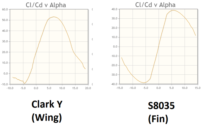
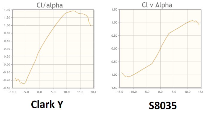
To illustrate this (not the tomatoes), see the below graphs:

See how the lift-drag ratio is better with the Clark Y section at an angle of attack of about 7º? And see how the S8035 produces much more negative lift at an alpha of ~-5º?
The same applies to tailplanes. You want your tailplane to produce negative lift, and a cambered section will happily do so while producing less drag. Efficient!
…
(the ellipsis implies a catch)
However:

Across a wide range of angles of attack from up to down, we know pretty well how the S8035 is going to perform. It’s got a fairly linear lift response and performs just the same at both positive and negative angles of attack, so both designing and flying the thing will be simpler. That’s not to mention actually shaping an aerofoil shape at such small sizes. If we just go for the S8035 section, life will simply be easier across the board.
Shake that Empennage
I wasn’t expecting tailplane aerofoil selection to go that quickly, so we might as well incapacitate a pair of avians with a single projectile.
As far as I’ve seen, most aircraft tend to go for strip rudders and elevators – that is, they span pretty much the whole lengths of their host sections. Sometimes the elevators have bits chopped out to prevent clashes with the rudder; sometimes it’s the other way around. This is a structural thing, and we can deal with it later.
Strip control surfaces can increase the risk of your servos getting damaged – if the end of the tailplane strikes the ground, for example, some of that force will be transmitted down the pushrods (the bits that connect your servos to your control surfaces) and could upset the multiple (often simple nylon) gears that allow the servo’s motor to get talking with that misplaced elevator. However, a projecting edge of balsa flown into the ground will simply snap, requiring an annoying repair job at fiddly scales. Servos and connecting pushrods also have a certain level of give in them, making those inevitable mishandling incidents a bit safer all round. Plus servos are cheap as chips to replace.
That just leaves us to figure out the chord of each control surface.
For the sake of mechanical simplicity, we’ll be tying our elevator and rudder chords together.
You know, there’s a very specific book by a very specific human person which I’m sure has this stuff written down… however it’s expensive and I don’t have it to hand. The internet is also being less helpful than usual in tracking down the relevant rules of thumb, though generally it looks like 20-25% is the norm for trainer-type models..
Going back to memory and… other sources… we’ll be setting our chords at 20%. This should provide us with sufficient control authority to get out of unpleasant situations without too much potential for dangerous over-controlling.
With the chord of the fin and tailplane already set at 0.14m:
Rudder Chord = ElevatorChord = 0.14 x 0.2 = 0.028
Let’s round that up to 0.03m.
Where That
Right then, last thing to round up: where is the tail actually going?
This question will need to be answered so we can figure out how much fuselage/boom we’ll need to have supporting the tail. It’s more of a structural question at this point, but we might as well answer it now.
Up until this point, we’ve just been treating the tail moment as an abstract number. We’re going to give it some meaning.
A few posts ago we determined that the tail moment arm should be…
Ahem. It seems I have been leaving the “arm” part out of the term in previous posts. It seems I may have some editing to do.
Shit.
To clarify: moment is Force x Distance. It’s pretty important for levers. Moment arm, by comparison, is kind of another name for distance.
In fact, let’s just go back to saying “distance”.
So, to recap: what I had been calling “tail moment” is the distance between the aircraft’s centre of gravity and the aerodynamic centre (see Basics of Wings Part 3) of the tail.
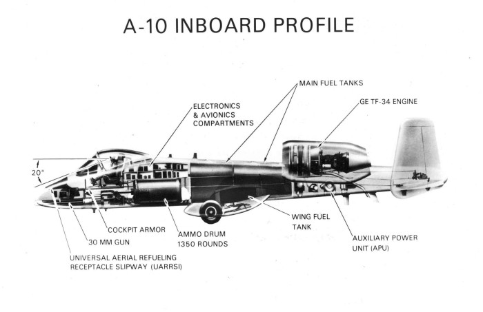
The centre of gravity, as a general rule of thumb, usually sits around 25-33% along the wing chord. Or it might be easier to say that the wing’s leading edge usually sits about 25-33% of its chord length ahead of the CG. It kind of depends how you want to think about it – the CG is the pivot, and the whole aircraft is built around it. Like how the A-10 is basically a plane built around a gun.

Either way, we’ve already established that a forward CG makes for a more stable aircraft, so let’s go with 25%.
The aerodynamic centre of a symmetrical aerofoil will sit at it’s thickest point – this usually ends up being 25% along its length.
Tallying up our lengths:
Wing chord = 0.27m
Tail chord = 0.14m
Tail moment arm/Distance from CG to tail aerodynamic centre = 0.54m
CG = 25% along wing chord

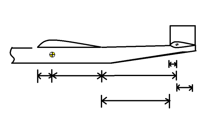
I really don’t know why I indicated so many potential measurement points here. The only interesting unknown here is how much fuselage lies between the wing’s trailing edge and the tail’s leading edge.
I mean, I say “interesting”… there’s a sharp thing at the front with magnets and shit that spins around hundreds of times a second and will happy fuck up whatever you feed it and scream for more. CG distancing? Tape measure-level junk. But it is kind of important. Botching the CG measurements can have results which can either be hilarious or appalling, depending on whether you’re flying a model or a full-scale aircraft. There’s a lot of stuff in aircraft that, if borked, will ruin not just your day but probably also someone else’s. It’s one of the greater reasons why aircraft are so damned expensive.
Ok, whatever. Numbers now.
Aaaaaaand I’ve put too much text between picture and maths, so now trying to write is difficult. Let’s post that picture again.

Tail moment arm = Distance from CG to wing trailing edge + distance from wing TE to tail leading edge + distance from tail LE to tail aerodynamic centre
Rearranging for the variable we seek:
Distance from WTE to TLE = TMA – Distance from CG to WTE – distance from TLE to TAC
Plugging in the known value of tail moment arm:
Distance from WTE to TLE = 0.54 – Distance from CG to WTE – distance from TLE to TAC
Distance from CG to wing trailing edge = 0.75 x Wing Chord = 0.75 x 0.27 = 0.2
Distance from TLE to TAC = 0.25 x Tail Chord = 0.25 x 0.14 = 0.035m
Therefore:
Distance from wing trailing edge to tail leading edge = 0.54 – 0.2 – 0.035 = 0.305
Round that to 0.31m, and we have our number.
Well that only took freaking forever.
What’s next? I don’t know. Electronics? RC stuff? Structure? Unified theory of everything?
Answers will surely come in time. Probably also space, because reasons.